Messaufbau mit Arduino: Gyroskop
Author: Syed Rafsan Ishtiaque
Art: Praxissemester
Dauer: 02.05.2023 - 21.08.2023
Betreuer: Prof. Dr.-Ing Ulrich Schneider
Einleitung
Das Gyroskop-Projekt wird es uns ermöglichen, die Daten einer kontinuierlichen Drehung eines Gyroskops zu erfassen und sie zur Analyse an unsere Steuereinheit zu senden. In diesem Projekt werden wir das Gyroskop drehen und seine Daten über einen Schleifring übertragen. Das Hauptaugenmerk des Projekts liegt darauf, die Daten an das DS1104 R&D Controller Board zu senden. Und dafür brauchen wir ein robustes System, das einen Schleifring und einen Encoder enthält. Die größte Herausforderung beim Aufbau des Systems ist die Hardware-Montage. Wir werden uns also mehr darauf konzentrieren.
Anforderungen
| ID | Inhalt | Ersteller | Datum | Geprüft von | Datum |
|---|---|---|---|---|---|
| 1 | Ein Haltebereich für PCB zwischen der Hauptstruktur und der Gyro-Struktur | Marc Ebmeyer | 27.07.2023 | ||
| 2 | Ein Servomotor (SG 90) zum Drehen des Gyroskops, des Rades des Inkrementalgebers und des Schleifrings | Marc Ebmeyer | 27.07.2023 | ||
| 3 | Einem Inkrementalgeber (FC 03) zur Messung der Drehung des Servomotors (SG 90) und des Gyro (GY 35) | Marc Ebmeyer | 27.07.2023 | ||
| 4 | Ein Gyro (GY 35), der in der gleichen Achse wie das Servo und der Schleifring platziert ist und über einen Draht mit dem Schleifring verbunden ist | Marc Ebmeyer | 27.07.2023 | ||
| 5 | Ein Schleifring (SN M022A-06), der über eine Welle mit dem Servo verbunden ist, um die Daten vom Gyro zu übertragen | Marc Ebmeyer | 27.07.2023 | ||
| 6 | |||||
| 7 | |||||
| 8 |
Funktionaler Systementwurf/Technischer Systementwurf
-
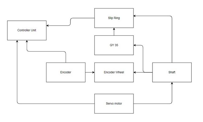 Abb. 2: Dieser Entwurf zeigt die Wechselwirkungen zwischen den Komponenten des Systems

Komponentenspezifikation (Elektronische Komponenten)
Sensor
GY-35-RC one-axial Gyroscope/ Analog ENC-03RC
Der Sensor, den wir verwenden werden, hat die Modellnummer GY-35. Auf ihm ist ein ENC-03RC-Chip montiert. Der GY-35 ist ein einachsiges Gyromodul, das heißt, ein Modul kann nur eine Achse messen. Die Spannungsversorgung beträgt 3 bis 5 V. Die Größe beträgt 10mm × 17.5mm [1] [2]. Eine Alternative zum Sensor GY 35 kann der Sensor MPU 6050 oder GY 521 sein.
Servo motor
Wir haben den normalen Servomotor, der normalerweise in Arduino-Projekten verwendet wird, so verändert, dass er sich kontinuierlich um 360 Grad drehen kann. Wir verwenden Tower Pro micro servo 9g SG90.
Umsetzung (Hardware)
Umsetzung (Software)
Programmierung
Link zum Quelltext in SVN
Systemtest
Komponententest
Test im Labor
Projektunterlagen
Projektplan
Hardware
Sensor
GY-35-RC one-axial Gyroscope/ Analog ENC-03RC
Servo motor
Wir haben den normalen Servomotor, der normalerweise in Arduino-Projekten verwendet wird, so verändert, dass er sich kontinuierlich um 360 Grad drehen kann. Wir verwenden Tower Pro micro servo 9g SG90.
Slip ring
Adafruit mini slip ring is a good option
Rotary connector
It will be over the capacity of the servo to rotate.
HC 05 Bluetooth module
It is also a possibility but for that we need a stronger servo motor. Because we have to mount not only the HC05 bluetooth connected with the GY 35 on the servo, we need another ADC module as the analog output fro the GY35 has to be converted into Digital signal to pass over the Bluetooth module. Also the price of the Bluetooth module HC05 is cheaper than the Adafruit mini slip ring, but then the cost in Servo will go up as we will need a better servo motor.
First Draft of Hardware assembly
We can use some kind of rotary module that can make the connection between GY35 and the Arduino. The rotary connector or slip ring approach could be a good way to solve the wire entanglement issue as we need continuous 360 degree rotation. The slip ring must have at least 4 rings or channels, one for each connection (VCC, GND, OUT and REF) between the GY-35 sensor and the Arduino. First we will mount the rotary part of the slip ring on the servo motor. Then we will mount the GY-35 on the rotary part of the slip ring so that it rotates with the servo motor. Now we will connect (VCC, GND, OUT and REF) of the GY35 with different ring/channel on the slip rings of the rotary part of the slip ring. Then the other side of the slip ring to the Arduino, matching the connections from the sensor side. Now, when the servo motor rotates the sensor and slip ring, the electrical connections to the Arduino will be maintained without the wires getting tangled.
So we have:
- Servo motor: Tower Pro Micro Servo 9g SG90 (3 to 5 euro depending buying quantity)
- Gyroscope: GY 35 ENC 03-RC (3 to 5 euro)
- And we can use Adafruit mini slip ring (Need to purchase):
- 12 mm, 6 wires = 20 euro apprx.
- 22 mm, 6 wires = 17 euro apprx.
LC and RC filter for noise cancellation
For the GY35 sensor when it will be connected with the Slip ring, we are expecting noises (high & low frequency) that can abrupt the system. To get rid of it, we are planning to introduce a noise cancellation system. Our initial plan is to make a circuit or sub-system that will have a set of 3 capacitors and 2 inductors on the GY35-Slip Ring side of the main system. We will also make a similar setup on the Slip Ring- Arduino side of the system. These two sets of decoupling capacitors will help us to reduce the noise and stabilize the power supply. Each set of capacitors will consist of one 0.1 µF, one 1 µF and one 10 µF capacitor. We will be using ceramic capacitors. The lowest valued capacitor (0.1 µF) will be placed near to the GY35 to filter out high frequency noise. Then the middle one (1 µF) and then the last one (10 µF) to filter out the low frequency noise. Probably we will use the general ceramic capacitors.
Then we will have the inductor, two of them. They will repel the high frequency noises along with the capacitors. This will make a LC filter for noise cancellation. For now we want to test our system with various valued inductors (e.g. ranging from 10 to 100 µH). The will be in series with the Vcc and the GND. Our proposal is to use the ferrite bead as they are good with high frequency noise cancellation.
Another important aspect, we will implement a RC low level filter. It will get rid of the noise from the analog output of the GY35. For that we primarily selected a pair of ??KΩ resistor and ??nF Capacitor (apprx.) [we used the cut off frequency calculation , Cut off frequency = 1/(2πRC)] or ?? KΩ resistor and ??nF Capacitor (apprx.) This values of the Resistor and Capacitor of the RC filter will depend on the cut off frequency that we need to achieve. For the capacitor in the RC filter we might use the film capacitors, because our aim is to filter the signal, and the ceramic ones are good with power.
Now we need to order the circuit elements for our project.
Zusammenfassung
Literature
→ zurück zum Hauptartikel: Messaufbauten mit Arduino