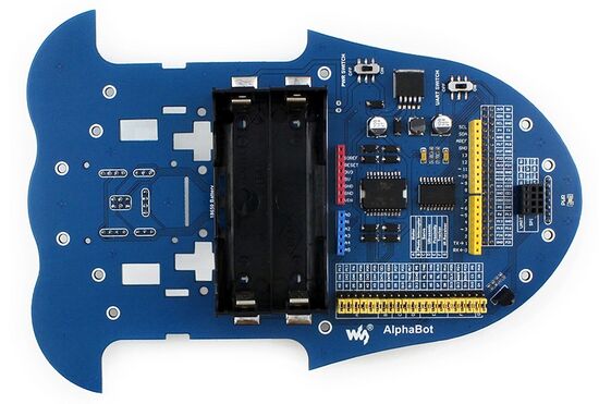
AlphaBot Hauptplatine: Unterschied zwischen den Versionen
Zur Navigation springen
Zur Suche springen
Keine Bearbeitungszusammenfassung |
|||
| (6 dazwischenliegende Versionen von 2 Benutzern werden nicht angezeigt) | |||
| Zeile 7: | Zeile 7: | ||
{| class="wikitable" | {| class="wikitable" | ||
|+ style = "text-align: left"|Tabelle 1: Komponenten der AlphaBot Hauptplatine | |+ style = "text-align: left"|Tabelle 1: Komponenten der AlphaBot Hauptplatine | ||
| Zeile 38: | Zeile 16: | ||
|<big><big>②</big></big> || Arduino Interface: für den Anschluss eines Arduino | |<big><big>②</big></big> || Arduino Interface: für den Anschluss eines Arduino | ||
|- | |- | ||
|<big><big>③</big></big> || | |<big><big>③</big></big> || Motor Interface | ||
|- | |- | ||
|<big><big>④</big></big> || | |<big><big>④</big></big> || Ultraschall Module Interface | ||
|- | |- | ||
|<big><big>⑤</big></big> || | |<big><big>⑤</big></big> || Servo Modul Interface | ||
|- | |- | ||
|<big><big>⑥</big></big> || | |<big><big>⑥</big></big> || Infrarot-Abstandssensor Interface | ||
|- | |- | ||
|<big><big>⑦</big></big> || | |<big><big>⑦</big></big> || Odometrie Interface | ||
|- | |- | ||
|<big><big>⑧</big></big> || | |<big><big>⑧</big></big> || Akkufach: für Akkus des Typs 18650 | ||
|- | |- | ||
|<big><big>⑨</big> || | |<big><big>⑨</big> || Reserve Spannungseingang (nicht verlötet): zum Anschluss einer externen Spannungsquelle | ||
|- | |- | ||
|<big><big>⑩</big></big> || | |<big><big>⑩</big></big> || Arduino Erweiterung: für den Anschluss von Arduino-Shields | ||
|- | |- | ||
|<big><big>⑪</big></big> || | |<big><big>⑪</big></big> || UART Interface: für den Anschluss eines [https://www.waveshare.com/wiki/Bluetooth_Slave_UART_Board Bluetooth Moduls] (Achtung bescriftung falsch am 5V Pin liegen 3,3V) | ||
|- | |- | ||
|<big><big>⑫</big></big> || | |<big><big>⑫</big></big> || SPI Interface: für den Anschluss eines [https://www.waveshare.com/wiki/NRF24L01_RF_Board_(A) NRF24L01 Funkmoduls] | ||
|- | |- | ||
|<big><big>⑬</big></big> || | |<big><big>⑬</big></big> || Linienverfolgungsssensor Interface | ||
|- | |- | ||
|<big><big>⑭</big></big> || | |<big><big>⑭</big></big> || [https://www.waveshare.com/wiki/TLC1543_ADC_Board TLC1543]: 10-bit ADU, ermöglicht es dem Pi analoge Sensoren einzulesen | ||
|- | |- | ||
|<big><big>⑮</big></big> || | |<big><big>⑮</big></big> || [https://docs.rs-online.com/92c1/0900766b8135fb62.pdf L298P]: Duale H-Brücke, Motortreiber bis zu 2A | ||
|- | |- | ||
|<big><big>⑯</big></big> || | |<big><big>⑯</big></big> || Anti-Reverse Diode | ||
|- | |- | ||
|<big><big>⑰</big></big> || | |<big><big>⑰</big></big> || Netzschalter | ||
|- | |- | ||
|<big><big>⑱</big></big> || | |<big><big>⑱</big></big> || [https://www.ti.com/lit/gpn/lm2596 LM2596]: 5V Spannungsregler | ||
|- | |- | ||
|<big><big>⑲</big></big> || | |<big><big>⑲</big></big> || Netzanzeige | ||
|- | |- | ||
|<big><big>⑳</big></big> || | |<big><big>⑳</big></big> || UART Schalter: einschalten, um Serial Communication zwischen Raspberry Pi und Arduino zu ermöglichen | ||
|- | |- | ||
| | |<big>㉑</big> || IR Empfänger: Steuerung des AlphaBot über eine IR-Fernbedienung | ||
|- | |- | ||
| | |<big>㉒</big>|| Raspberry Pi/Arduino Steckbrücke: Auswahl, ob der Raspberry Pi oder Arduino die Roboterperipherie ansteuert. | ||
|- | |- | ||
|} | |} | ||
| Zeile 83: | Zeile 61: | ||
* [https://www.waveshare.com/product/robotics/mobile-robots/alphabot-pi3-b-plus.htm Waveshare Homepage] | * [https://www.waveshare.com/product/robotics/mobile-robots/alphabot-pi3-b-plus.htm Waveshare Homepage] | ||
* [https://www.waveshare.com/wiki/AlphaBot Waveshare Wiki: AlphaBot] | * [https://www.waveshare.com/wiki/AlphaBot Waveshare Wiki: AlphaBot] | ||
* [https://wiki.hshl.de/wiki/index.php/AlphaBot_Sensorbr%C3%BCcken Sensor Brücken] | |||
* [https://www.waveshare.com/w/upload/b/b1/AlphaBot_Schematic.pdf AlphaBot Mainboard Schaltplan] | |||
---- | ---- | ||
→ zurück zum Hauptartikel: [[AlphaBot Bauanleitung#Ben.C3.B6tigte_Bauteile|AlphaBot Bauanleitung]] | → zurück zum Hauptartikel: [[AlphaBot Bauanleitung#Ben.C3.B6tigte_Bauteile|AlphaBot Bauanleitung]] | ||
Aktuelle Version vom 26. Juni 2024, 11:37 Uhr

Autoren: Prof. Dr.-Ing. Schneider
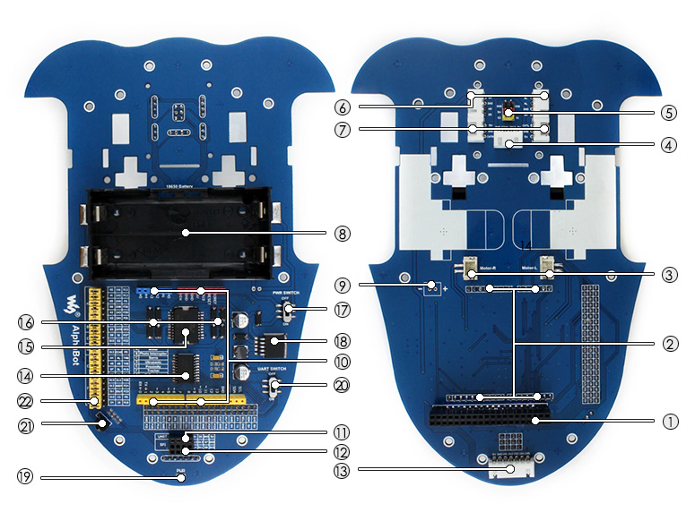
Übersicht

| # | Beschreibung |
|---|---|
| ① | Raspberry Pi Interface: für den Anschluss eines Raspberry Pi |
| ② | Arduino Interface: für den Anschluss eines Arduino |
| ③ | Motor Interface |
| ④ | Ultraschall Module Interface |
| ⑤ | Servo Modul Interface |
| ⑥ | Infrarot-Abstandssensor Interface |
| ⑦ | Odometrie Interface |
| ⑧ | Akkufach: für Akkus des Typs 18650 |
| ⑨ | Reserve Spannungseingang (nicht verlötet): zum Anschluss einer externen Spannungsquelle |
| ⑩ | Arduino Erweiterung: für den Anschluss von Arduino-Shields |
| ⑪ | UART Interface: für den Anschluss eines Bluetooth Moduls (Achtung bescriftung falsch am 5V Pin liegen 3,3V) |
| ⑫ | SPI Interface: für den Anschluss eines NRF24L01 Funkmoduls |
| ⑬ | Linienverfolgungsssensor Interface |
| ⑭ | TLC1543: 10-bit ADU, ermöglicht es dem Pi analoge Sensoren einzulesen |
| ⑮ | L298P: Duale H-Brücke, Motortreiber bis zu 2A |
| ⑯ | Anti-Reverse Diode |
| ⑰ | Netzschalter |
| ⑱ | LM2596: 5V Spannungsregler |
| ⑲ | Netzanzeige |
| ⑳ | UART Schalter: einschalten, um Serial Communication zwischen Raspberry Pi und Arduino zu ermöglichen |
| ㉑ | IR Empfänger: Steuerung des AlphaBot über eine IR-Fernbedienung |
| ㉒ | Raspberry Pi/Arduino Steckbrücke: Auswahl, ob der Raspberry Pi oder Arduino die Roboterperipherie ansteuert. |
Weiterführende Links
→ zurück zum Hauptartikel: AlphaBot Bauanleitung