Using the Raspberry Pi’s GPIO to control hardware components
The Raspberry Pi's row of GPIO pins along the top edge of the board is a powerful feature. General-Purpose Input/Output is an acronym for GPIO. These pins are the Raspberry Pi's physical interface to the outside world. You can think of them as switches that you can turn on or off (input) or that the Pi can turn on or off (output) at the most basic level (output). The Raspberry Pi's GPIO pins link to electronic circuits and allow it to control and monitor the outside world. The Raspberry Pi can control LEDs, switch them on and off, and run motors, among other things. It can also tell if a switch has been pressed, the temperature, and the amount of light. This is referred to as physical computing.

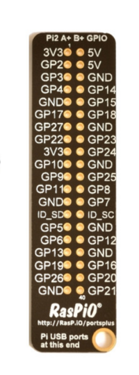
The Raspberry Pi has 40 pins (26 pins on early variants), each of which serves a different purpose. If you have a RPi pin label, you can use it to assist you figure out what each pin is for. Make that the keyring hole on your pin label is facing outwards, away from the USB ports.
1. GND: Zero volts is a voltage that is used to complete a circuit.
2. GP2: These pins can be used for a variety of purposes and can be set up as input or output pins.
3. 5V: Anything that is attached to these pins will always receive 5 volts of power.
4. 3V3: Anything attached to these pins will receive 3.3V power at all times.
5. ID_SC/ID_SD/DNC: pins with a specific purpose.
TIP: Playing with the GPIO pins is safe and enjoyable if you follow the instructions. Randomly putting wires and power sources into a Pi, on the other hand, may cause it to fail, especially if the 5V pins are used. If you try to connect devices to a Pi that use a lot of power, bad things can happen.
An ultrasonic distance sensor emits ultrasound pulses that are undetectable by humans and detects the echo that is returned when the sound bounces off a nearby object. The distance from that thing is then calculated using the speed of sound.
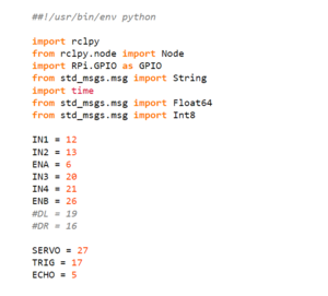
Two GPIO pins (one for echo, one for trigger), the ground pin, and a 5V pin are connected to the circuit. You must know which GPIO pins the echo and trigger are attached to in order to use the ultrasonic distance sensor in Python. First, we initialize the GPIO pins in our program.
Here,
- the echo is connected to pin '5'
- the trigger is connected to pin '17'
- the servo to pin '27'.

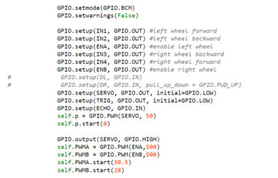
GPIO.setmode(GPIO.BCM) = set up GPIO Broadcom chip-specific pin numbering
self.p = GPIO.PWM(servo, 50) = When RPi configured for software pulse-width modulation, each pin generates a square waveform with a configurable duty cycle and frequency
self.PWMA.start ( ) = hints left wheel speed
self.PWMB.start ( ) = hints right wheel speed
