Verwaiste Dateien
Zur Navigation springen
Zur Suche springen
Bitte beachte, dass andere Webseiten eine Datei mit einer direkten URL verlinken können. Sie könnte daher hier aufgelistet sein, obwohl sie in aktiver Verwendung ist.
Unten werden bis zu 250 Ergebnisse im Bereich 251 bis 500 angezeigt.
-
 Plot Gierrate.fig ; 356 KB
-
-
Plot nach Offline Sim org.fig ; 259 KB
-
Laengsfuehrung test.mdl ; 72 KB
-
-
Plot Messung org.fig ; 555 KB
-
Plot.fig ; 1,58 MB
-
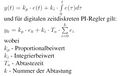 Reglergleichung.JPG 953 × 606; 69 KB
-
 Tfuzjugh.jpeg 2.448 × 1.836; 376 KB
-
 Lolllllllllllllllllllll.jpeg 2.448 × 1.836; 376 KB
-
 Asdgs.jpeg 2.448 × 1.836; 376 KB
-
 KreisbahnG03.gif 256 × 207; 2 KB
-
 KreisbahnG02.gif 256 × 207; 2 KB
-
 Schaltplan LEDWuerfel.pdf ; 546 KB
-
VariablenLaden.m ; 2 KB
-
Einspurmodell Solo BSF org.mdl ; 137 KB
-
LED.pdf 0 × 0; 270 KB
-
Silberdraht.pdf 0 × 0; 41 KB
-
8 Bit Schieberegister.pdf 0 × 0; 283 KB
-
N-MOSFET.pdf 0 × 0; 366 KB
-
KONDENSATOR 22PF.pdf 0 × 0; 35 KB
-
TANTAL KONDENSATOR.pdf 0 × 0; 37 KB
-
KONDENSATOR 1UF.pdf 0 × 0; 35 KB
-
SMD WIDERSTAND.pdf 0 × 0; 528 KB
-
LOWDROP.pdf 0 × 0; 313 KB
-
Treiber Empfänger.pdf 0 × 0; 308 KB
-
Standardquarz.pdf 0 × 0; 206 KB
-
 LidarRange.png 600 × 400; 14 KB
-
LidarRange Quelle.zip ; 10 KB
-
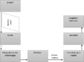
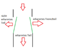
 Objekterkennung.png 777 × 1.706; 62 KB
-
Objekterkennung.vsdx ; 37 KB
-
-
 Schaltplan Shield1.JPG 1.407 × 887; 114 KB
-
-
Schwingungsmethode bestimmen.zip ; 12 KB
-
Präsentation Temp Regelung V2.0.pptx ; 1,62 MB
-
Datenblaetter.zip ; 335 KB
-
Bilder-Originaldateien.zip ; 247 KB
-
Ansteuerung WS 2014.zip ; 1,49 MB
-
-
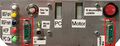
 Hardware.png 1.059 × 585; 989 KB
-
 HSHL2.JPG 4.000 × 4.000; 398 KB
-
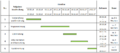
 Gantt-Diagramm.JPG 734 × 1.217; 129 KB
-
 CycleChaser.png 510 × 371; 214 KB
-
-
-
 Bild2.png 583 × 444; 435 KB
-
 Bild3.png 297 × 594; 191 KB
-
 Bild1.png 407 × 296; 354 KB
-
 Schaltplan Arduino Schrittmotortreiber Schrittmotor.PNG 1.154 × 785; 112 KB
-
 G00.JPG 429 × 353; 32 KB
-
 G01.JPG 559 × 595; 55 KB
-
Wochenplan GET Praktikum.pdf 0 × 0; 13 KB
-
 Schaltplan LTL.PNG 1.366 × 768; 215 KB
-
 Steckplatine LTL.PNG 1.366 × 768; 263 KB
-
 Steckplatine DLTL.PNG 1.366 × 768; 271 KB
-
 Steckplatine DLTL1.PNG 1.366 × 768; 235 KB
-
 Arduino Leiterplatte oben.JPG 980 × 735; 252 KB
-
 GUI Steuerung.JPG 502 × 492; 48 KB
-
-
 ProjektplanBrickPi.pdf 1.809 × 353; 155 KB
-
 Projektplanung Ballbalancierer 01 Jan Voellmecke.jpg 3.441 × 1.097; 1.020 KB
-
 Sensorkonzept Testmontage 1.jpg 252 × 448; 36 KB
-
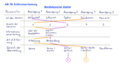
Keyless Entry37b Gantt-Chart.pdf 0 × 0; 15 KB
-
Atmega328 master.ino ; 3 KB
-
 Einheitssprung Sprungantwort.png 1.397 × 720; 35 KB
-
 Setup raspberrypi.PNG 839 × 505; 8 KB
-
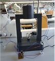 Projekt49 Versuchsaufbau.JPG 350 × 388; 32 KB
-
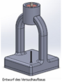 Projekt49 CAD Modell.png 625 × 843; 392 KB
-
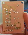 Leiterplatte.JPG 316 × 399; 22 KB
-
 Projekt 49 Standfuß geduckt.JPG 310 × 395; 15 KB
-
 Komponenten.png 653 × 587; 144 KB
-
 2 übersicht.png 854 × 691; 76 KB
-
 Schraubendruckfeder cut.png 982 × 523; 131 KB
-
 20160108 194709 klein.jpg 1.000 × 563; 114 KB
-
 Verbesserungsmöglichkeiten.jpg 955 × 553; 95 KB
-
 Oben.jpg 563 × 1.000; 106 KB
-
 Halterung.jpeg 1.885 × 2.497; 809 KB
-
 Gesamtmodell.png 944 × 349; 16 KB
-
Gesammtmodell.pptx ; 34 KB
-
 AMR13 Gyrosignal Auswahl X Z.png 1.393 × 1.240; 122 KB
-
 AMR13 Gyrosignal Verstaerkung Z.png 1.393 × 1.240; 122 KB
-
 AMR13 Gyrosignal Verstaerkung X.png 1.393 × 1.240; 122 KB
-
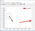 Neue Richtung.jpg 702 × 629; 75 KB
-
 Model2.png 399 × 292; 13 KB
-
 Dobble berechne Median.PNG 743 × 430; 18 KB
-
 Dobble Bildumwandlung.PNG 444 × 207; 7 KB
-
 Dobble ermittle Grenzen.PNG 628 × 185; 8 KB
-
 Dobble extrahiere Karten.PNG 451 × 75; 3 KB
-
 Dobble finde Objekte.PNG 456 × 61; 3 KB
-
 Dobble fülle Löcher.PNG 563 × 125; 5 KB
-
 Dobble Hintergrund.PNG 595 × 419; 18 KB
-
 Dobble Kreisförmigkeit.PNG 521 × 192; 7 KB
-
 Dobble speicher Kreise.PNG 473 × 121; 3 KB
-
 Dobble speicher Parameter.PNG 510 × 192; 10 KB
-
 Dobble iteriere Kinder.PNG 516 × 134; 5 KB
-
 Schlüssel in karte.jpg 678 × 599; 23 KB
-
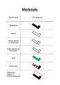 Merkmale.jpg 1.241 × 1.754; 157 KB
-
 24V DC.JPG 735 × 980; 236 KB
-
 Neues Netzteil 24VDC.JPG 735 × 980; 236 KB
-
 Objekt und Spurerkennung.PNG 837 × 399; 25 KB
-
 Spurpolynomberechnung.png 1.098 × 1.323; 202 KB
-
 4 Achse.jpg 592 × 507; 203 KB
-
 Projektplan Projekt 62.jpg 1.534 × 462; 145 KB
-
 Meilensteinplan.JPG 850 × 473; 132 KB
-
 Ultraschallsensor.JPG 1.344 × 1.008; 36 KB
-
 Beispiel.jpg 300 × 230; 10 KB
-
PAPFälle.png 7.368 × 5.779; 1,64 MB
-
 Funktionale AnforderungenP64.PNG 788 × 265; 15 KB
-
DBFotowiderstand.pdf 0 × 0; 155 KB
-
DBTemperatursensor.pdf 0 × 0; 119 KB
-
Summer.pdf 0 × 0; 95 KB
-
LEDblau.pdf 0 × 0; 213 KB
-
LEDgrün.pdf 0 × 0; 160 KB
-
DBAttiny85.pdf 0 × 0; 635 KB
-
 Lidar Objekterkennung und Tracking.png 2.479 × 2.434; 470 KB
-
 Lidar screenshot.jpg 379 × 506; 26 KB
-
 Projektplan-P64-Wasserstandswarner.gif 1.746 × 571; 67 KB
-
 BillofMaterial.PNG 1.684 × 178; 42 KB
-
 Oszillogramme.jpg 6.592 × 2.803; 677 KB
-
 Messplatine Multisimschaltung.jpg 1.212 × 756; 291 KB
-
 Projekt Mitsubishi Timeline.PNG 872 × 383; 19 KB
-
 Projekt Mitsubishi Pufferbatterie Roboterarm.PNG 559 × 412; 37 KB
-
 Mitsubishi Projekt Batterie Steuergerät.PNG 595 × 395; 31 KB
-
 Mitsubishi Projekt Batterie Steuergerät1.PNG 597 × 134; 6 KB
-
 Mitsubishi Projekt Zurücksetzung Batterie Timer.PNG 606 × 415; 42 KB
-
 Mitsubishi Projekt Versorgungsspannung.PNG 596 × 255; 25 KB
-
 Mitsubishi Projekt Anforderungen.PNG 1.190 × 470; 35 KB
-
 Projekt Mitsubishi Tägliche Inspektionspunkte.PNG 623 × 349; 20 KB
-
 Projekt Mitsubishi Periodische Inspektionspunkte.PNG 623 × 346; 19 KB
-
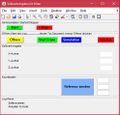
 GUI.JPG 502 × 480; 59 KB
-
 2016-11-11-NX-16200-000-A-Schnittansicht.JPG 1.600 × 693; 156 KB
-
 Nutstoßen.jpeg 899 × 997; 126 KB
-
 Morfologischer.jpg 1.784 × 996; 354 KB
-
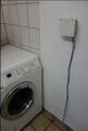 Wasserstandswarner-Waschküche.JPG 663 × 985; 57 KB
-
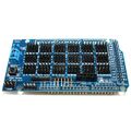 Sensor-shield-20-sensor-expansions-board-fuer-arduino-mega-2560.jpg 1.200 × 1.200; 893 KB
-
-
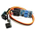
 Schleifenempfaenger-kit-perimeter-receiver-kit.jpg 1.200 × 1.200; 532 KB
-
 I2C-Netzwerk - sensorgesteuerte Ampelschaltung2.png 813 × 424; 98 KB
-
 Home.jpg 960 × 720; 80 KB
-
 HomeAutomationPlatine.jpg 960 × 720; 56 KB
-
 HomeAutomationPlatine2.jpg 960 × 720; 69 KB
-
 HomeAutomationPlatine2.JPG 960 × 720; 69 KB
-
 Verkabelung Master.jpg 560 × 857; 88 KB
-
 Schaltung Projekt 62.gif 1.857 × 690; 194 KB
-
 SSR Problem.png 435 × 229; 390 KB
-
 Programm.JPG 611 × 604; 48 KB
-
 P49-Versuchsaufbau.jpg 2.984 × 5.312; 212 KB
-
 20160108 143341.jpg 2.988 × 3.024; 1,12 MB
-
 P49 Platine.JPG 2.349 × 1.196; 635 KB
-
 Foto 20.12.16, 13 27 33.jpg 2.110 × 2.834; 793 KB
-
 Platineeins.jpg 3.264 × 2.448; 1,21 MB
-
 49-qrcode.jpeg 400 × 400; 30 KB
-
 2017-01-06 22.14.14 2.jpg 2.976 × 5.312; 1,42 MB
-
 2017-01-06 22.14.12-min.jpg 2.976 × 5.312; 1,45 MB
-
 Projekt Mitsubishi Grundposition Aufkleber.PNG 585 × 261; 23 KB
-
 Projekt Mitsubishi Schritt1.PNG 704 × 484; 54 KB
-
 Projekt Mitsubishi Eingabe Grundpositionsdaten.PNG 705 × 164; 13 KB
-
 Projekt Mitsubishi Dateneingabe Grundposition Teil1.PNG 559 × 467; 53 KB
-
 Projekt Mitsubishi Dateneingabe Grundposition Teil2.PNG 555 × 469; 54 KB
-
 Projekt Mitsubishi Programmierbefehle Teil1.PNG 453 × 598; 85 KB
-
 Projekt Mitsubishi Programmierbefehle TEil2.PNG 447 × 627; 81 KB
-
 Projekt Mitsubishi Programmierbefehle Teil2b.PNG 446 × 465; 56 KB
-
 Projekt Mitsubishi Programmierbefehle Teil3.PNG 451 × 221; 33 KB
-
 Projekt Mitsubishi Programmierbefehle Teil4.PNG 447 × 364; 52 KB
-
 Schaltungsrealisierung mit Steckplatine.jpg 960 × 720; 158 KB
-
 Caseplan.svg 815 × 709; 12 KB
-
 Arduino mit Hc05.png 1.080 × 1.920; 49 KB
-
 Programmablaufplan SPS Achsensteuerung.png 858 × 1.377; 46 KB
-
 Hardwarekonfiguration step7.png 1.366 × 768; 103 KB
-
Schaltplan SPS CNC.pdf 0 × 0; 362 KB
-
 QR Code Ergebnisvideo.JPG 410 × 410; 618 Bytes
-
 Projektplan 3D Drucker German RepRap.jpg 1.837 × 393; 172 KB
-
 Static qr code without logo.jpg 330 × 330; 410 Bytes
-
 Schaltplan SIEKMANN DICK.png 1.384 × 938; 55 KB
-
 Messestand 1.JPG 2.744 × 1.543; 1,24 MB
-
 Außengehäuse.jpg 660 × 370; 57 KB
-
SPS-Grundlagen.pdf 0 × 0; 1,08 MB
-
 GPE-Labor.JPG 1.024 × 243; 58 KB
-
 Überprüfung Schrittmotoren.JPG 3.264 × 2.448; 1,57 MB
-
 Uberpruf.JPG 3.264 × 2.448; 1,57 MB
-
 Aufgabenliste.jpg 1.696 × 460; 204 KB
-
 Pinbelegung von 37 D´Sub Pin auf 25 D´Sub Pin.jpeg 714 × 574; 131 KB
-
BOM06.jpg ; 15 KB
-
Timeline.xlsx ; 12 KB
-
-
Technisches-Handbuch.pdf 0 × 0; 1,73 MB
-
-
 16231034 1354876421211281 1165658464 o.jpg 2.048 × 1.536; 420 KB
-
 16215802 1354882127877377 1690252298 n.png 600 × 447; 472 KB
-
 Mitsubishi Projekt Systemübersicht.png 600 × 447; 472 KB
-
 Mitsubishi Projekt Systemübersicht1.png.jpg 2.048 × 1.536; 420 KB
-
 PM SÜ.jpg 2.048 × 1.536; 420 KB
-
 GUI mit Log-Panel nach oeffnen.jpg 494 × 475; 62 KB
-
 Powerpanel Laden.png 3.143 × 1.202; 1,81 MB
-
 Schrittkette motortreiber ansteuern.png 600 × 725; 24 KB
-
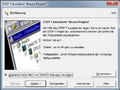 Einrichtungsassistent.png 473 × 356; 49 KB
-
 Hardware config oeffnen.png 1.366 × 726; 38 KB
-
 Hardware update auswählen.png 1.366 × 728; 103 KB
-
 Hardware konfiguration.png 1.366 × 728; 76 KB
-
 Cp340 parametrieren.png 718 × 503; 41 KB
-
 Db20 erstellen.png 1.366 × 727; 69 KB
-
 DB20 füllen.png 1.366 × 726; 70 KB
-
 Db1 erstellen.png 1.366 × 727; 71 KB
-
 Symboltabelle erstellen.png 1.366 × 726; 41 KB
-
 Ob1 oeffnen.png 1.366 × 727; 42 KB
-
 Platine sps.jpg 1.200 × 1.600; 206 KB
-
 PAP Stopplinienerkennung.png 1.647 × 1.776; 281 KB
-
 Ausgabe Stopplinienerkennung.png 722 × 492; 386 KB
-
 Pinbelegungen.JPG 532 × 414; 83 KB
-
 Aufbau SIMENS SPS.png 693 × 487; 44 KB
-
 Modulare-sps-57.jpg 690 × 370; 46 KB
-
 PHÖNIXSPS.png 568 × 248; 263 KB
-
 Legoteil Zaehlmaschine Sortierung PAP.png 774 × 1.763; 184 KB
-
 Thorsten Drees.jpg 757 × 708; 125 KB
-
 Ardumower Hauptplatine.jpg 2.902 × 1.646; 1.001 KB
-
 Roboter2.jpg 469 × 439; 26 KB
-
 Tabelle Messfehler.png 553 × 584; 24 KB
-
 Us modul2.png 1.500 × 1.125; 1,34 MB
-
 Beispie.jpg 759 × 410; 41 KB
-
 SRF05 Zeilverlauf ohne Verzögerung.png 780 × 427; 37 KB
-
 Port Error.jpg 2.448 × 3.264; 1,39 MB
-
 None.jpg 2.448 × 3.264; 1,41 MB
-
 UltrasonicMessabweichung.PNG 553 × 350; 11 KB
-
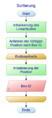
 Funktionsflussdiagramm.png 1.081 × 771; 36 KB
-
 Morphologischer Kasten-SS17.png 2.193 × 1.118; 305 KB
-
 Bewertung.png 4.412 × 2.789; 1,83 MB
-
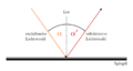 Reflexionsgesetz.png 1.058 × 562; 17 KB
-
Dokumentation InfP2B5 2017.docx ; 17 KB
-
 Fahrzeug Seite-min.jpg 4.608 × 3.456; 792 KB
-
 Datei 30.06.17, 12 32 28.jpeg 3.264 × 2.448; 1,62 MB
-
 LEGO Mindstorms Programm.svg 5.082 × 1.443; 134 KB
-
 Grafik Bildgröße.pdf 1.180 × 717; 32 KB
-
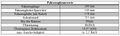 Fahrzeugkennwerte.JPG 627 × 189; 38 KB
-
 Roboter Gruppe A1 SoSe17 (1).jpg 3.689 × 3.457; 1,97 MB
-
 Roboter Gruppe A1 SoSe17 1.jpg 3.689 × 3.457; 1,97 MB
-
 Ablaufplan snip.JPG 639 × 903; 70 KB
-
 IMG 1531.JPG 1.920 × 1.280; 646 KB
-
 Profil.jpg 2.983 × 2.984; 1,43 MB
-
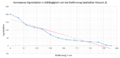 Diagramm.S1.PNG 814 × 393; 30 KB
-
 Sortierung Trichter.PNG 289 × 412; 4 KB
-
 Sortierung Vorsortierung.PNG 658 × 558; 11 KB
-
 Sortierung Drehmomentübertragung.PNG 737 × 458; 12 KB
-
Case 0 Lücke finden.png 8.214 × 6.915; 1,86 MB
-
 Sortierung Abbremsung.PNG 778 × 421; 33 KB
-
 Sortierung Klappenlagerung.PNG 820 × 568; 7 KB
-
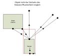
 Us erfassungsbereich.png 288 × 261; 61 KB
-
 Fügekonzept.png 561 × 333; 4 KB
-
 Rotary-anatomy.png 794 × 542; 25 KB
-
 Sortierung Drehmomentübertragung Alternative.PNG 625 × 443; 111 KB


.jpg)


