Modellsimulation in Webots und Simulationen mit ROS2: Unterschied zwischen den Versionen
| Zeile 25: | Zeile 25: | ||
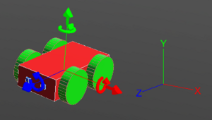
The co-ordinate system of the robot works exactly as the picture above depicts. The red arrow shows the X-axis and it defines the right and left of the robot. The green arrow shows the Y-axis and it can be used to move the robot upwards and downwards. The blue arrow is the Z-axis and it is related to forward and backward movement of the robot. By default the co-ordinates system is turned off in Webots. It can be turned on by following these steps: "''View >> Optional Rendering >> Show Coordinate System''" or by simply pressing "''Ctrl+F1''". | The co-ordinate system of the robot works exactly as the picture above depicts. The red arrow shows the X-axis and it defines the right and left of the robot. The green arrow shows the Y-axis and it can be used to move the robot upwards and downwards. The blue arrow is the Z-axis and it is related to forward and backward movement of the robot. By default the co-ordinates system is turned off in Webots. It can be turned on by following these steps: "''View >> Optional Rendering >> Show Coordinate System''" or by simply pressing "''Ctrl+F1''". | ||
'''Top View in a Grid''' | |||
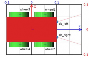
[[Datei:dimensions_grid.png|thumb|links|mini|300px|Abb. 3 - Co-ordinates]] | |||
<br clear=all> | |||
The figure above shows the top view of the robot. It is inside a grid to understand the dimensions of the robot. The dimension of the grid is 0.2 × 0.3 meters. | |||
=== Demo-Programs === | === Demo-Programs === | ||
Version vom 9. Februar 2022, 13:40 Uhr
Autoren: Arfat Kamal
Betreuer: Prof. Schneider
Art: Praxissemester
Projektlaufzeit: 02.11.2021-20.02.2022

Introduction
In order to simulate, a 3D model of a 4 wheeled robot is created inside Webots first. That robot is simulated with a controller which is written in C inside the text editor of Webots. That robot is later imported in Webots in Ubuntu and customised with a servo, an ultrasonic sensor and a caster wheel to resemble the Alphabot robot of our project. Finally, it is programmed with ROS2 and it runs in Webots as an obstacle avoiding robot.
Overview
Documentation
Creation of a 3D Model of a 4-Wheeled-Robot in Webots

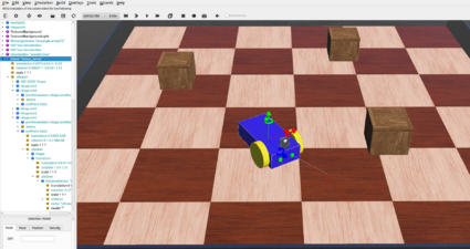
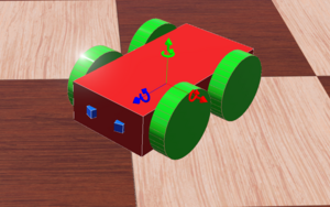
A 4-Wheeled-Robot is created in Webots from scratch by following tutorial 6 in Cyberbotics. The robot consistes of a body, 4 wheels and two distance sensors(IR sensors). The figure above shows the 3D view of the end result.
Co-ordinate System

The co-ordinate system of the robot works exactly as the picture above depicts. The red arrow shows the X-axis and it defines the right and left of the robot. The green arrow shows the Y-axis and it can be used to move the robot upwards and downwards. The blue arrow is the Z-axis and it is related to forward and backward movement of the robot. By default the co-ordinates system is turned off in Webots. It can be turned on by following these steps: "View >> Optional Rendering >> Show Coordinate System" or by simply pressing "Ctrl+F1".
Top View in a Grid

The figure above shows the top view of the robot. It is inside a grid to understand the dimensions of the robot. The dimension of the grid is 0.2 × 0.3 meters.
Demo-Programs
Software
Summary
Weiterführende Links
→ zurück zum Hauptartikel: Praxissemester Projektteam WS2021