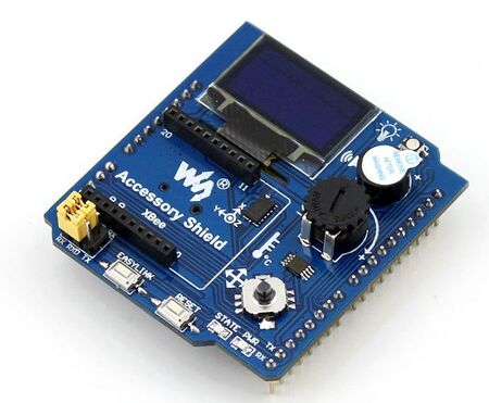
AlphaBot Accessory Shield


Übersicht
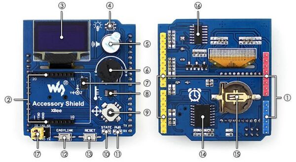
| Pos. | Beschreibung |
|---|---|
| ① | Arduino IO Steckverbindung |
| ② | XBee Interface |
| ③ | 0.96inch OLED, 128×64 Pixel |
| ④ | RGB LED |
| ⑤ | Piezo Lautsprecher |
| ⑥ | 10 kΩ Potentiometer |
| ⑦ | 3-Achsen-Beschleunigungssensor, ± 16g |
| ⑧ | Temperatursensor LM75BDP |
| ⑨ | 5-Wege-Joystick |
| ⑩ | XBee Statusanzeige |
| ⑪ | Spannungs-LED |
| ⑫ | XBee EASYLINK Taster |
| ⑬ | Arduino und XBee RESET Taster |
| ⑭ | Echtzeituhr DS3231 |
| ⑮ | CR1220 Batteriehalter |
| ⑯ | RGB LED Treiber P9813 |
| ⑰ | Steckprücken (Debug/Kommunikation) |
Hinweis zu 17: Connecting TXD to TX, and RXD to RX, the XBee module can be debugged and configured by the relative software installed on the PC via the serial port on the Arduino main control board; Connecting TXD to RX, and RXD to TX, the XBee module can communicate with the Arduino main control board via the serial port.
Bibliotheken einbinden
Den Artikel zum Einbinden der Bibliotheken für die Multisensorerweiterung finden Sie hier.
Dateien
Datenblätter
Software
Weiterführende Links
→ zurück zum Hauptartikel: AlphaBot Bauanleitung