Nicht kategorisierte Dateien
Zur Navigation springen
Zur Suche springen
Unten werden bis zu 50 Ergebnisse im Bereich 951 bis 1.000 angezeigt.
-
 Anker.jpg 3.024 × 4.032; 1,71 MB
-
 Ankerpositionierung.jpg 658 × 439; 18 KB
-
 Anlage.png 1.280 × 960; 842 KB
-
 Anlage Beschriftet.png 854 × 557; 64 KB
-
 AnleitungK1.JPG 1.199 × 942; 131 KB
-
 AnleitungK2.JPG 2.204 × 434; 106 KB
-
 Anleitung Fahrzeugbau Gruppe C4.zip ; 5,48 MB
-
 Anleitung Installation Matlab2013b LegoSupportPackage Dateiliste.JPG 651 × 299; 41 KB
-
 Anleitung Nullposition.pdf 0 × 0; 251 KB
-
Anleitung Panopto Videobearbeitung fuer Studierende.pdf 0 × 0; 1,58 MB
-
Anleitung Panopto fuer Studierende.pdf 0 × 0; 1,28 MB
-
 Anleitung S-Funktion1.PNG 995 × 281; 21 KB
-
 Anleitung S-Funktion2.PNG 443 × 335; 11 KB
-
 Anleitung S-Funktion3.PNG 1.208 × 905; 230 KB
-
 Anleitung S-Funktion4.PNG 778 × 694; 80 KB
-
 Anleitung S-Funktion5.PNG 480 × 426; 64 KB
-
 Anleitung S-Funktion7.PNG 576 × 510; 53 KB
-
Anleitung zu Panopto Aufgabenordner .pdf 0 × 0; 288 KB
-
-
 Anode Kathode.png 225 × 394; 5 KB
-
 Anordnung der Komponenten auf dem Board.png 779 × 368; 296 KB
-
 Anpassung Sensorinitialisierung.PNG 1.153 × 458; 54 KB
-
 Anpassung der Zeit.png 867 × 1.828; 178 KB
-
 Ansatz mit Arduino.png 848 × 852; 152 KB
-
 Ansatz mit Atmel.png 1.648 × 1.566; 297 KB
-
Anschlag.PDF 0 × 0; 39 KB
-
 Anschlag Testaufbau.PNG 252 × 337; 193 KB
-
 AnschlussVibrationsantrieb.png 1.824 × 1.356; 195 KB
-
 Anschluss Antriebs-Akku.jpg 1.024 × 768; 89 KB
-
 Anschluss CANoe.jpg 3.831 × 1.862; 1,42 MB
-
 Anschluss ConnectBox.jpg 2.634 × 1.895; 1,73 MB
-
 Anschluss Tempmessung an Steuerung.png 414 × 708; 376 KB
-
 Anschluss der Komponenten.png 1.110 × 699; 238 KB
-
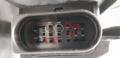
 Anschlussbelegung CY-100(1).PNG 680 × 239; 15 KB
-
 Anschlussbelegung CY-100.PNG 265 × 99; 5 KB
-
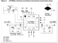 Anschlussbelegung LPY530AL.PNG 872 × 653; 70 KB
-
 Anschlussbelegung Steuereingang PiCo Regelgerät.PNG 654 × 171; 52 KB
-
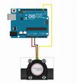
 Anschlussbild Sound Sensor.png 924 × 465; 75 KB
-
 Anschlussbild Wasser Durchflussensor.jpg 883 × 956; 150 KB
-
 Anschlusspins Schema Spannungsversorgung.png 2.016 × 980; 1,93 MB
-
 Anschlussplan.png 1.211 × 694; 586 KB
-
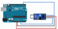
 Anschlussplan Arduino.png 2.342 × 1.657; 116 KB
-
 Anschlussplan HC-SR04.png 1.248 × 745; 83 KB
-
 Anschlussplan Schrittmotor.jpg 651 × 695; 96 KB
-
 Anschlussplan Sharp.png 874 × 535; 77 KB
-
 Anschlussplan Sound Sensor.png 790 × 499; 46 KB
-
 Anschlussplan TMP36.jpg 1.007 × 1.185; 211 KB
-
 Anschlussplan der Druckdose.PNG 759 × 511; 76 KB
-
 Anschlussplan des magnetisch-induktiven Durchflussmessers.PNG 779 × 324; 22 KB
-
 Anschlussplan von der Pneumatischer Absperrklappe.PNG 440 × 683; 23 KB


.PNG)