Nicht kategorisierte Dateien
Zur Navigation springen
Zur Suche springen
Unten werden bis zu 50 Ergebnisse im Bereich 501 bis 550 angezeigt.
-
Abb. 1 Systementwurf.png 3.821 × 3.821; 226 KB
-
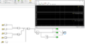 Abb1.png 1.037 × 566; 72 KB
-
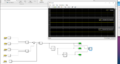 Abb2.png 1.715 × 914; 270 KB
-
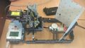 Abb3.jpg 1.292 × 728; 237 KB
-
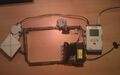 Abb4.jpg 1.337 × 840; 191 KB
-
Abbiegen.mp4 ; 39,97 MB
-
Abbiegen1.mp4 ; 4,65 MB
-
Abbiegen2.mp4 ; 3,84 MB
-
Abbiegen beim Rundkurs.mp4 ; 6,88 MB
-
Abbiegen beim Rundkurs mit Kreuzung.mp4 ; 4,31 MB
-
 Abbiegen beim Rundkurs ohne Kreuzung.mp4 1.568 × 508; 113 KB
-
-
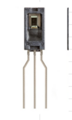 Abbildung-7-Honeywell Feuchtigkeitssensor.png 151 × 252; 20 KB
-
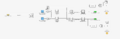
 Abbildung1- Schaltplan.jpeg 2.448 × 1.836; 376 KB
-
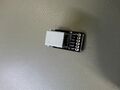 Abbildung2-Gehäuse.jpeg 2.448 × 1.836; 400 KB
-
 Abbildung 10 - Funktionsdarstellung der Station Kleben.png 943 × 4.423; 478 KB
-
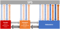 Abbildung 11 - technischer Systementwurf.PNG 1.407 × 678; 125 KB
-
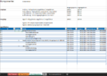 Abbildung 12 - Komponentenspezifikation am Beispiel der Klebestation.PNG 1.060 × 747; 56 KB
-
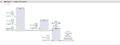 Abbildung 13 - Beispielbaustein Programmierung.PNG 1.127 × 425; 18 KB
-
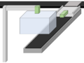 Abbildung 1 - Visualisierung der Station.PNG 1.036 × 777; 20 KB
-
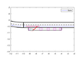 Abbildung 2- Simulation ohne Änderungen.png 560 × 420; 9 KB
-
 Abbildung 2 - Gesamtkonzept der MPS-Anlage.png 1.350 × 1.080; 905 KB
-
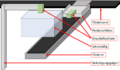 Abbildung 3 - Darstellung der benötigten Komponenten der Station.PNG 1.292 × 751; 51 KB
-
 Abbildung 4 - Darstellung der Deckenplatte.jpg 3.024 × 4.032; 3,08 MB
-
 Abbildung 5 - Darstellung einer Seitenscheibe.jpg 3.024 × 4.032; 3,85 MB
-
 Abbildung 6 - Darstellung einer Käfigsäule.jpg 3.024 × 4.032; 2,71 MB
-
 Abbildung 7 - Darstellung des Käfiggestell.jpg 3.024 × 4.032; 2,35 MB
-
 Abbildung 8.png 944 × 124; 39 KB
-
 Abbildung 8 - Darstellung des aufgebauten Schutzkäfigs.PNG 735 × 685; 470 KB
-
 Abbildung 9.png 964 × 110; 49 KB
-
 Abbildung 9 - Anforderungsdefinition.PNG 1.008 × 743; 69 KB
-
 Abbildung ABB IRB1400 Arbeitsraum Industrieroboter.png 1.772 × 1.122; 271 KB
-
 Abbildung ABB IRB1400 Dreipunktgreifer iso.jpg 3.414 × 3.413; 1,37 MB
-
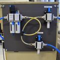 Abbildung ABB IRB1400 Druckluftaufbereitung vorne.jpg 3.000 × 2.999; 1,6 MB
-
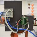 Abbildung ABB IRB1400 Efekktor-Steuerung vorne.jpg 3.000 × 3.000; 1,6 MB
-
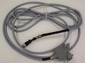 Abbildung ABB IRB1400 Kabel Robotersteuerung.jpg 4.000 × 3.000; 1,91 MB
-
 Abbildung ABB IRB1400 Kabel Schnittstelle.JPG 4.000 × 3.000; 1,19 MB
-
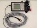 Abbildung ABB IRB1400 Kabel Teachpendant.JPG 4.000 × 3.000; 1,63 MB
-
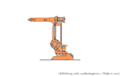 Abbildung ABB IRB1400 Kalibrierposition.png 1.772 × 1.122; 120 KB
-
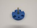 Abbildung ABB IRB1400 Kalibrierspitze.JPG 3.825 × 2.869; 1,06 MB
-
 Abbildung ABB IRB1400 Parallelgreifer iso.jpg 3.466 × 3.466; 1,23 MB
-
 Abbildung ABB IRB1400 RoboDK Programm erstellen 01.PNG 964 × 733; 274 KB
-
 Abbildung ABB IRB1400 RoboDK Programm erstellen 02.PNG 967 × 760; 243 KB
-
 Abbildung ABB IRB1400 RoboDK Programm erstellen 03.PNG 1.190 × 751; 342 KB
-
 Abbildung ABB IRB1400 RoboDK Programm erstellen 04.PNG 1.413 × 1.040; 141 KB
-
 Abbildung ABB IRB1400 RoboDK Programm erstellen 05.PNG 1.171 × 985; 138 KB
-
 Abbildung ABB IRB1400 RoboDK Programm erstellen 06.PNG 913 × 710; 16 KB
-
 Abbildung ABB IRB1400 RoboDK Programmierung 01.PNG 1.156 × 879; 123 KB
-
 Abbildung ABB IRB1400 RoboDK Programmierung 02.PNG 1.154 × 879; 228 KB
-
 Abbildung ABB IRB1400 RoboDK Programmierung 03.PNG 998 × 762; 316 KB


