Modellsimulation in Webots und Simulationen mit ROS2: Unterschied zwischen den Versionen
| Zeile 308: | Zeile 308: | ||
[[Datei:IR_Robot.png|thumb|left|mini| | [[Datei:IR_Robot.png|thumb|left|mini|450px|Fig. 29: IR Robot]] | ||
<br clear=all> | <br clear=all> | ||
After finishing all the modifications, our new robot for IR Obstacle Avoidance looks like the Figure 29. | After finishing all the modifications, our new robot for IR Obstacle Avoidance looks like the Figure 29. | ||
[[Datei:IR_Obstacle_Avoidance.mp4|thumb|left|mini| | [[Datei:IR_Obstacle_Avoidance.mp4|thumb|left|mini|450px|Video 2: IR Obstacle Avoidance]] | ||
<br clear=all> | <br clear=all> | ||
Video 2 is an example of simulation of Obstacle Avoidance with IR using ROS2. | Video 2 is an example of simulation of Obstacle Avoidance with IR using ROS2. | ||
Version vom 20. März 2022, 19:16 Uhr
Autoren: Arfat Kamal
Betreuer: Prof. Schneider
Art: Praxissemester
Projektlaufzeit: 02.11.2021-20.02.2022
Introduction
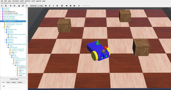
In order to simulate, a 3D model of a 4 wheeled robot is created inside Webots first. That robot is simulated with a controller which is written in C inside the text editor of Webots. That robot is later imported in Webots in Ubuntu and customised with a servo, an ultrasonic sensor and a caster wheel to resemble the Alphabot robot of our project. Finally, it is programmed with ROS2 and Python to run it in Webots as an obstacle avoiding robot.
Overview
Documentation
3D Model of a 4-Wheeled-Robot
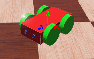
A 4-Wheeled-Robot is created in Webots from scratch by following tutorial 6 in Cyberbotics. The robot consists of a body, 4 wheels and two distance sensors(IR sensors). Figure 2. above shows the 3D view of the end result. Creating the 3D model of the 4 wheeled robot was the first milestone and it is a major step for the simulation of our project since the 3D model of the Alphabot is based on this model.
Co-ordinate System
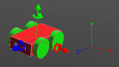
The co-ordinate system of the robot works exactly as the picture above depicts. The red arrow shows the X-axis and it defines the right and left of the robot. The green arrow shows the Y-axis and it can be used to move the robot upwards and downwards. The blue arrow is the Z-axis and it is related to forward and backward movement of the robot. By default the co-ordinates system is turned off in Webots. It can be turned on by following these steps to show the X, Y and Z axis:
View >> Optional Rendering >> Show Coordinate System
Or by simply pressing Ctrl+F1.
Top View in a Grid
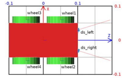
The figure above shows the top view of the robot. It is inside a grid to understand the dimensions of the robot. The dimension of the grid is 0.2 × 0.3 meters.
High Level Representation
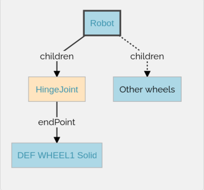
The picture above depicts the high level representation of the 4 wheeled robot. Here, Robot is the base node. The Robot node has four HingeJoint nodes. The HingeJoints are used as anchors to connect the wheels to the body of the robot. Each HingeJoint has a Solid node as endPoint. The Solid nodes are then modified into the wheels of the robot.
Low Level Representation
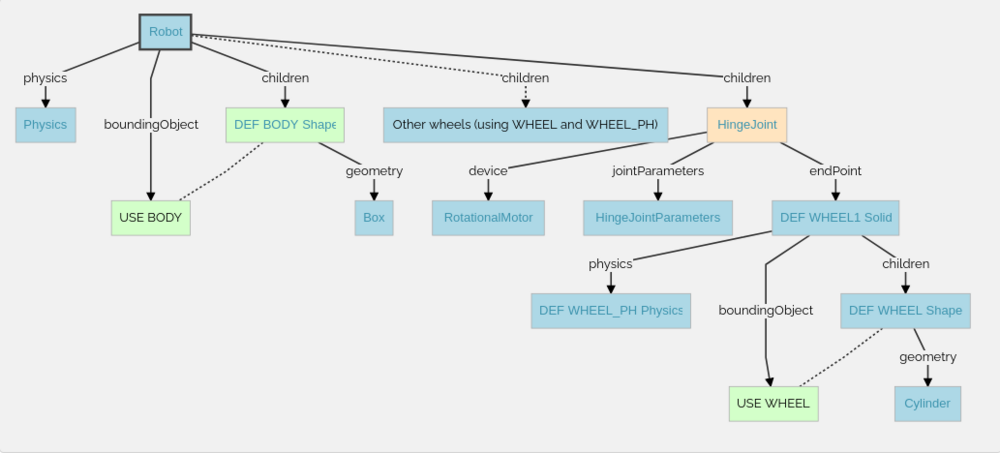
The figure above demonstrates the structure of the robot in details, how the 3D model is modeled in Weobts using the scene tree. The steps of the Low Level Representation will be explained in detail inside the 'Creating the 3D Model' section.
Representation of a HingeJoint
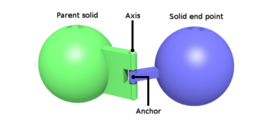
In Webots, whenever rotary or linear motion is used, we must use a HingeJoint. In our case, since we are using RotationalMotor for moving the wheels, HingeJoints are being used to anchor the wheels to the body. As we can see in the photo, Parent solid is in our case the body of the robot and wheels are attached as solid end points. In the HingeJoint node we also use RotationalMotor as a Device for moving the robot.
Sensors
In our case, two IR sensors are used to measure distance in the beginning for the 4-Wheeled-Robot. In Webots these sensors are found as DistanceSensors. There are four type of distance sensors in Webots. They are -
- Generic,
- Infra-red,
- Sonar,
- Laser.
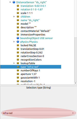
In Webots, these different types of distance sensors can be found inside DistanceSensor Node which is under the Children node of the Robot base node. There is an example in Figure. 8 that shows how to change between different types of Distance Sensors by selecting the 'type' field of DistanceSensor from the scene tree. Later when we use Ultrasonic Sensor for avoiding obstacles, we change the type of the DistanceSensor to Sonar.
Creating the 3D Model
Body
The first step to create the 3D model of the robot is to make the body. In order to create the body of the robot at first we add a Robot node as a base node inside the scene tree. Then inside the Robot node we have to go inside the Children node. Inside the Children node we again go inside the Base nodes. From Base nodes we add a Shape inside the scene tree. This shape should be transformed into the body of the robot.
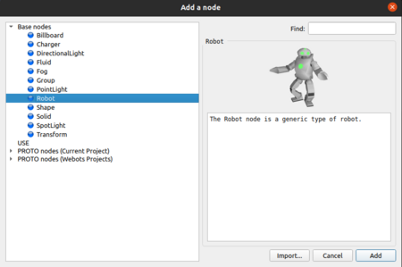
The above photo in Figure 9 shows how a Robot Node is added inside the scene tree by simply clicking on the 'add' icon from Webots terminal. The steps to add a shape inside the Robot node to make the body is given below:
Robot > Children > Base Nodes > Shape
Appearance
First we have to change the appearance of the shape. To do that we go inside the Shape from the scene tree and click on Appearance and choose PBRAppearance. Inside the Appearance Node, We can change the color by changing the baseColor which is in RGB format. We can also change the Metalness to 0 and the Rougness to 1 to make it look better.
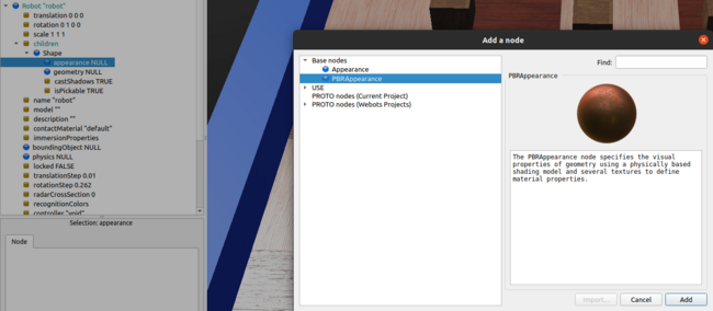
The above photo in Figure 10. shows how PBRAppearance is added as appearance of the Shape of the body of the Robot.
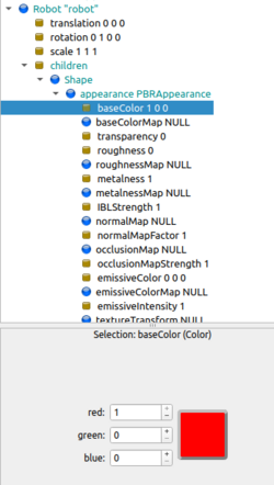
The Base Color of the robot can be set to Red by changing the RGB value of the BaseColor Node as it is shown in Figure 11. We do this by setting the value of Red to 1 and 0 to Green and Blue.
For changing the metalness of the body, we follow the following steps:
Robot > children > Shape > appearance > metalness > set to 0
The same way we can also change the roughness of the shape. We only change the metalness and roughness of the shape so the color appears better. The roughness can be changed by following the steps below:
Robot > children > Shape > appearance > roughness > set to 1
Geometry
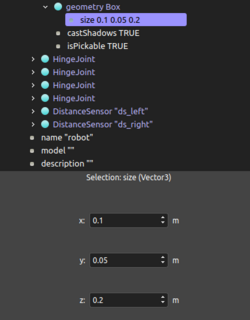
We need to give a geometry to the Shape of the robot. To do that we have to go inside the Shape Node and click on 'geometry'. Then we go inside Base nodes and choose 'Box' since the body of our Robot has the geometry of a box. We can also change the size of the box from 'geometry'. We simply select the 'size' field which is inside 'geometry'. There we can see three fields for changing the size of the box with x,y and z values. For our case, x is 0.1 m, y is 0.05 m and z is 0.2 m. The end result looks like the Figure 12 below.
DEF Mechanism
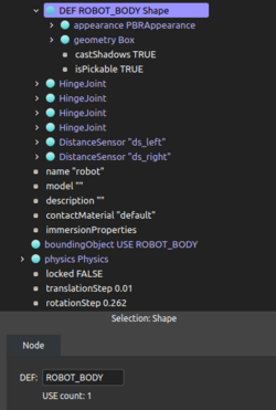
We have this 'DEF' option in Webots to Define something under a certain name. Which is helpful sometimes when we want to use the same values of something for something else, so we do not have to recreate everything from scratch. This is also helpful when we want to use a shape or something as a bounding object. In our case we defined the Shape that we turned into the body of the robot as 'Body'. We can do this by selecting the Shape node and writing 'Body' inside the empty field after 'DEF'. The 'DEF' field can be found right under the scene tree. A graphical representation of the DEF Mechanism can be found in the Figure 13. below.
BondingObject
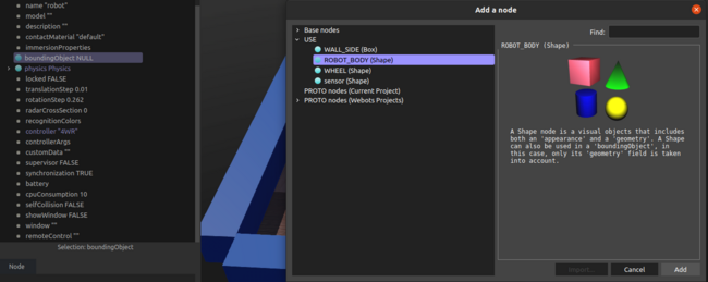
Once we define the Shape as the Body of the robot, we can select it as the bounding object of our robot. We use bounding object so other solid items from the world do not go inside the robot. We can do this by selecting the boundingObject field which is a part of the Robot base node. Once we select the boundingObject, We can go inside 'USE' and select the box shape that we created and defined as 'ROBOT_BODY'. Since the body of the robot is the biggest part of our robot, we choose this as the bounding object of the Robot Node. Figure 14. below demonstrates how BoundingObject can be selected in Webots.
Physics
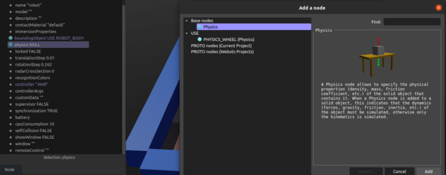
And lastly we change the Physics of the Robot Node from 'null' to 'physics.' Figure 15. below shows how physics is added to a node. We simply click on Physics, which is by default set to null. Then from the Base nodes we choose 'Physics'. Once we do this, physics is added to our robot node and we can see some attributes like density, mass, center of mass, are also added under the 'Physics' node in the scene tree. We do not have to make any changes to these attributes. We just leave them as it is.
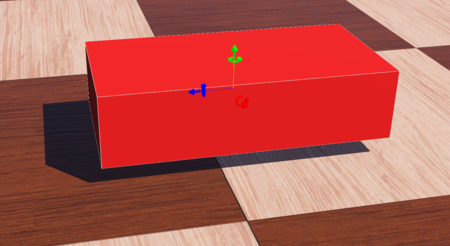
After doing all the changes to the Shape of the body, modifying the appearance, adding geometry and physics, the end result of the body of the robot looks like Figure. 16 below -
Wheels
HingeJoint
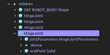
To add wheels to the Robot, firstly we need to add HingeJoints. Whenever we want to add something to the Robot, we must add it to the Children Node of the Robot Base Node. Adding HingeJoints is also done with the same procedure. For adding HingeJoint we have to click on 'add' while we are inside the Children Node. Then we just have to choose 'HingeJoint' from the options inside of Base Nodes.
Once we have added the HingeJoint, we have to configure the jointParameters, add a RotationalMotor as the device and add a solid as an endPoint as it is found in Figure 17.
JointParameters
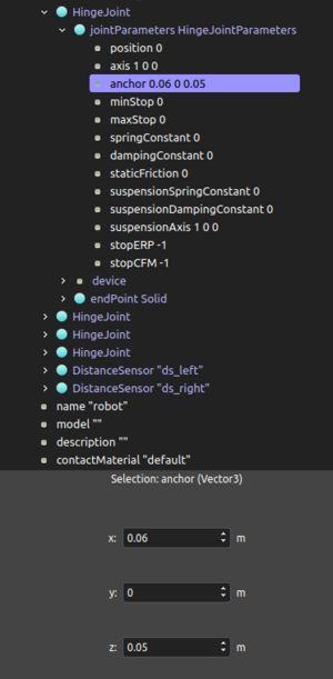
In jointParameters, the first thing we do is adding HingeJointParameters from the base nodes. This will allow us to manipulate the joint parameters attributes. We change the axis value to 1 in x direction and leave y and z to 0. We also need to change the x, y and z values of the anchor field. This should be the same as the position of the wheel. The anchor is set to 0.06m in x, 0m in y and 0.05m in z direction as it can be seen in Figure 18 above.
RotationalMotor
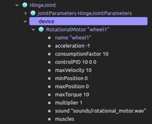
The motor to drive the wheel is also added inside the HingeJoint. To add a motor We go inside the HingeJoint Node, then we choose RotationalMotor from the 'device' field as Figure 19 depicts. Inside the 'RotationalMotor' node we need to give it a name. We name this as 'wheel1' as we are going to attach this motor to the first wheel along with the hingeJoint. The name is very important because we are going to use the exact same name later when we write the code to drive these motors.
Adding Wheels as Solid Nodes
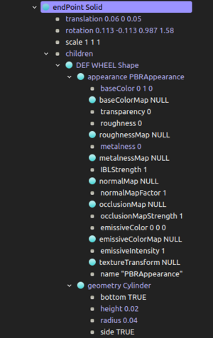
For adding the wheel to the HingeJoint, first we need to add a Solid Node to the endPoint of the HingeJoint Node. The Solid Node is then transformed into a wheel. To do that we have to add a shape from the Base Nodes of the Solid. Then we change the appearance of the shape from to null to PBRAppearance. We change the geometry to cylinder. Then we change the dimension of the wheel by changing the values of height and radius. The height of the wheel is set to 0.02 meters and the radius is set to 0.04 meters as it can be seen in Figure 20.
When we are done customizing the shape of the wheel, we can save all the customization by defining the wheel by using the 'DEF' field. This is an useful feature of Webots, because it will allow us to use the defined shape in the future when we want to add more wheels. We will not have to do all the customizations of the shape for the other wheels again. Here we define the wheel as 'WHEEL'.
Once we have defined it, we can use it now as a bounding object. To do that we go inside of 'endPoint Solid' Node. From there we select boundingObjects, then 'Use' and select Wheel. We can add physics to the wheel same way. By clicking on 'physics' and then choose 'Physics' from the Base Nodes.
After that we make some changes to the translation and rotation inside the 'endPoint' Node to select the position of the wheel in relation to the robot. The 'translation' field has 3 values - x, y and z. We change the x value to 0.06, y to 0 and z to 0.05. For the rotation we will change the z value to 1 and leave x and y to 0. For the angle we make it 1.57, which 90 degrees in radian. Figure 21. is a graphical representation of the fields where these changes take place.
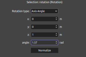
We can also change the color of the wheel by changing the baseColor. We can do it the same way we changed the color of the body. Only this time, we change the green value of the RGB field to 1, leave red and blue to 0. We also change the values of roughness and metalness same as before.
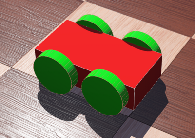
Once we are done adding the first wheel, adding the rest of the wheels become quite easy. Since we saved the first wheel from the 'shape' node by defining it with the 'DEF' field, now we can use the saved shape 'WHEEL' for all the other wheels. We just need to change the translation of the wheel for each wheel as it defines the position of the wheel on the Robot. For the second wheel, we just change the x value of the translation to -0.06, y and z remain the same as the first wheel. For the 3rd wheel the translation is - x: 0.06, y: 0, z: -0.05. For the 4th wheel the translation is - x: -0.06, y: 0, z: -0.05. Once the wheels are added, our robot so far looks like Figure 22 below.
Adding Distance Sensors
We add the DistanceSensors the same way as we added the other components. Inside the Robot node we go to the Children node and then we choose the 'DistanceSensors' from the Base Nodes. The steps to add a DistanceSensor is given below:
Robot > Children > Base nodes > DistanceSensor
Once we add the 'DistanceSensor' node to the scene tree, we need to make some changes to the translation and the rotation field. Because we are using two IR sensors as distance sensors initially for the 4 wheeled robot, so their position on the robot would be different. We are putting them in a slight angle so they can detect obstacles better at corners, that is why their rotation would also be different to each other.
For the first distance sensor, we set the translation for x to 0.02, 0 for y and 0.1 for z like the Figure 23 below. By setting the translation, we are actually defining where exactly the distance sensor should be positioned on the body of the robot.
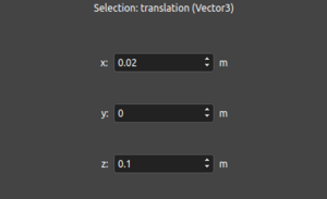
For the second distance sensor, we also do similar change to the translation field. The only difference is, the x field is negative. Instead of having 0.02 in x, we have -0.02 and the rest are the same.
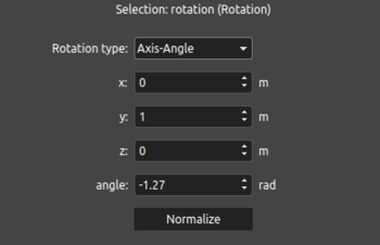
The Rotation node also has x, y and z values to manipulate and in addition it has a field for angle. Here we are changing the angle with respect to the y axis. That is why we write 1 in y and leave x and z to 0. The angle is in radian. For the first distance sensor we change the angle to -1.27 and the second one to -1.87. An example of the rotation field can be found in Figure 24 below.
We have a Children Node inside inside the DistanceSensor Node. As always we create a shape inside the Children, add and customize appearance, add geometry, boundingObjects and physics as we have done before. In the end the DistanceSensors look like the Figure 24 below. We also give them names by using the 'Name' attribute. We name the first sensor 'ds_left' and the second one 'ds_right'. The names are very important as these names are going to be used in the codes exactly how we name them.
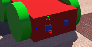
Simulation of 4 Wheeled Robot
The 3D model that we created in Webots is simulated afterwards with the controller code that is given in the Cyberbotics website in tutorial 6. An overview of the code is shown in Figure 25 below. The code is written in C and it makes the robot run as an obstacle avoiding robot.
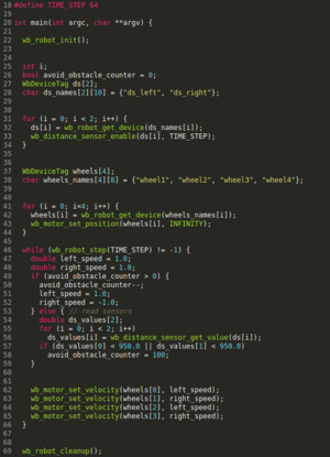
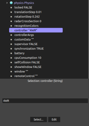
To write the controller code inside Webots, we go to Wizards, then choose 'Create Robot Controller'. Then we copy and paste the code inside the code editor. Then we have to save and build the file using the options above the text editor. Once we build the controller file, we have to choose it as the controller of the robot from the scene tree as it is shown in Figure 26. We named our controller file '4WR'. So we choose '4WR' from controller option.
Once we choose the controller to drive the robot, we can see how it works by starting the simulation. We can start the simulation by clicking on the play button, which can be found on the options on the top bar of the Webots interface. An example of the 4 Wheeled Robot simulation can be found in the video below.
Webots-ROS2 Installation
To use ROS2 to simulate our robot, we need to install Webots first in Linux environment. Because ROS2 (Robot Operating System 2) is better suited in Linux operating system. For that case our entire project has been done using Ubuntu 20.04 and ROS2 Foxy (a version of ROS2 which is compatible with Ubuntu 20.04). Webots for Ununtu can be downloaded from Github repository. For our project we are using the 2021b version.
After installing Webots, we can build our 'webots_ros2' package. This package is the parent ROS2 package which contains other packages like webots_ros2_driver, webots_ros2_core, and so on. The packages inside the 'webots_ros2' package help us to use ROS2 for simulating with Webots. There are some other packages inside the main package, like 'webots_ros2_epuck', 'webots_ros2_tiago', 'webots_ros2_tesla' and more, which are basically some other robots that can be simulated with webots-ros2. We also need to create a package of our own inside the 'webots_ros2' package in order to simulate our robot.
To build the 'webots_ros2' package, a workspace needs to be created first. This can be done by following this tutorial. Then we open a new terminal. We can do it simply by pressing the following keys -
Ctrl + alt + t
After opening a new terminal, the first thing we do is sourcing our ROS2 distro. Every time we open a new terminal, we always need to make sure that we source our distro. Otherwise, none of the ROS2 commands will work. We can source ROS2 by using the following command -
source /opt/ros/foxy/setup.bash
After that we need to clone the git repository of the 'webots_ros2' package. To do that we write the following code in the terminal -
git clone --recurse-submodules https://github.com/cyberbotics/webots_ros2.git src/webots_ros2
Once we have cloned the github repository of our package, we need to install some dependencies for our package to work without any errors. To install the dependencies we execute the following commands in the terminal -
rosdep update

rosdep install --from-paths src --ignore-src --rosdistro $ROS_DISTRO
After successfully installing the dependencies, we can build our package by using the 'colcon build' command. If we do everything fine and none of the dependencies are missing, we should see a message saying our package is built successfully. Otherwise, we will get an error message while trying to build the package.
If the package is built successfully, we should the source this workspace by executing any of the following commands -
 source install/local_setup.bash

 . install/setup.bash
This was the last step for building the 'webots_ros2' package. Once we source the workspace, our package is good to go. We can try out different robot simulations which were already inside the package and we can also create our own package to do simulation of our robot using ROS2.
IR Obstacle Avoidance with ROS2
Before doing the obstacle avoidance simulation with ROS2, we need to make some modifications to our 3D model of the 4 Wheeled Robot. We tried to make it more like the Alphabot of out project. Since the alphabot has two wheels, we also get rid of the two back wheels of the 3D model and add a caster wheel at the bottom back side to make it resemble the alphabot.
Adding a Caster Wheel to the 3D Model
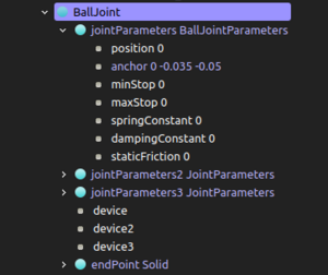
To add a caster wheel, first we need to add a BallJoint. We can add a BallJoint to the scene tree by following the step below -
Robot > Children > Add > Base Nodes > BallJoint
Once we add the BallJoint to our scene tree, we can see in Figure 26 that the BallJoint has three jointParamateres as opposed to the HingeJoint, which had just one jointParameter. For the first jointParameter of BallJoint, we need to add the anchor parameters of x, y and z with respect to the position of the robot body. For the second and third jointParameter, we only change the axis value. In this case, the second joint axis is x: 0, y: 0 and z: 1, and the third joint axis is x: 0, y: 1 and z: 0.
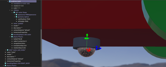
After configuring the jointParameteres of the BallJoint, we can add the CasterWheel as a shape inside the endPoint Solid node of the BallJoint. Figure 27 is a graphical representation of how it looks once it is done and how it is done inside the scene tree. We add a shape in the children node of the endPoint Solid, give it an appearance, change its translation and rotation, give it a geometry of a sphere, add boundingObject and Physics, doijng all the same steps as before.
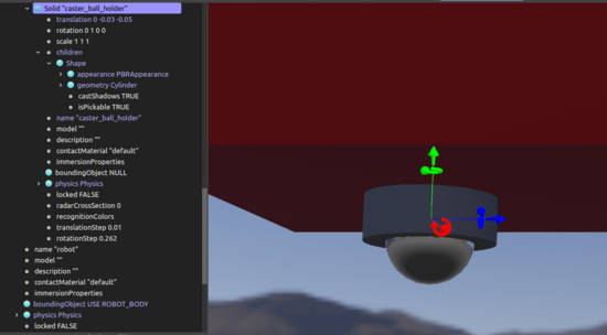
We also add a Caster Wheel Holder to hold the Caster Wheel in position. We do it by adding a new Solid node and making a shape inside that node. We do it similarly as we made the Caster Wheel. But this time, we use 'cylinder' in Geometry as opposed to 'sphere' - which we used for the Caster Wheel.
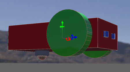
After finishing all the modifications, our new robot for IR Obstacle Avoidance looks like the Figure 29.
Video 2 is an example of simulation of Obstacle Avoidance with IR using ROS2.
Demo-Programs
Software
Summary
Weiterführende Links
→ zurück zum Hauptartikel: Praxissemester Projektteam WS2021