Modellsimulation in Webots und Simulationen mit ROS2: Unterschied zwischen den Versionen
Keine Bearbeitungszusammenfassung |
Keine Bearbeitungszusammenfassung |
||
| Zeile 9: | Zeile 9: | ||
== Introduction == | == Introduction == | ||
In order to simulate, a 3D model of a 4 wheeled robot is created inside Webots first. That robot is simulated with a controller which is written in C inside the text editor of Webots. That robot is later imported in Webots in Ubuntu and customised with a servo, an ultrasonic sensor and a caster wheel to resemble the [https://wiki.hshl.de/wiki/index.php/AlphaBot/ Alphabot] robot of our project. Finally, it is programmed with ROS2 and it | In order to simulate, a 3D model of a 4 wheeled robot is created inside Webots first. That robot is simulated with a controller which is written in C inside the text editor of Webots. That robot is later imported in Webots in Ubuntu and customised with a servo, an ultrasonic sensor and a caster wheel to resemble the [https://wiki.hshl.de/wiki/index.php/AlphaBot/ Alphabot] robot of our project. Finally, it is programmed with ROS2 and Python to run it in Webots as an obstacle avoiding robot. | ||
== Overview == | == Overview == | ||
Version vom 15. Februar 2022, 11:32 Uhr
Autoren: Arfat Kamal
Betreuer: Prof. Schneider
Art: Praxissemester
Projektlaufzeit: 02.11.2021-20.02.2022
Introduction
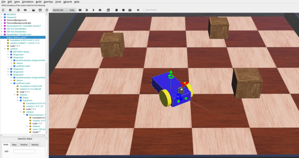
In order to simulate, a 3D model of a 4 wheeled robot is created inside Webots first. That robot is simulated with a controller which is written in C inside the text editor of Webots. That robot is later imported in Webots in Ubuntu and customised with a servo, an ultrasonic sensor and a caster wheel to resemble the Alphabot robot of our project. Finally, it is programmed with ROS2 and Python to run it in Webots as an obstacle avoiding robot.
Overview
Documentation
Creation of a 3D Model of a 4-Wheeled-Robot
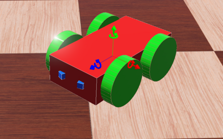
A 4-Wheeled-Robot is created in Webots from scratch by following tutorial 6 in Cyberbotics. The robot consists of a body, 4 wheels and two distance sensors(IR sensors). The figure above shows the 3D view of the end result.
Co-ordinate System
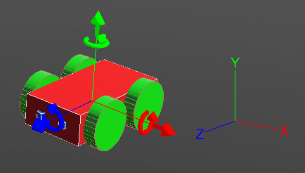
The co-ordinate system of the robot works exactly as the picture above depicts. The red arrow shows the X-axis and it defines the right and left of the robot. The green arrow shows the Y-axis and it can be used to move the robot upwards and downwards. The blue arrow is the Z-axis and it is related to forward and backward movement of the robot. By default the co-ordinates system is turned off in Webots. It can be turned on by following these steps to show the X, Y and Z axis:
View >> Optional Rendering >> Show Coordinate System
Or by simply pressing Ctrl+F1.
Top View in a Grid
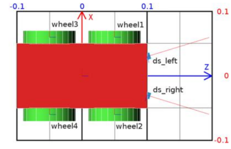
The figure above shows the top view of the robot. It is inside a grid to understand the dimensions of the robot. The dimension of the grid is 0.2 × 0.3 meters.
High Level Representation
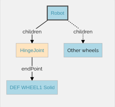
The picture above depicts the high level representation of the 4 wheeled robot. Here, Robot is the base node. The Robot node has four HingeJoint nodes. The HingeJoints are used as anchors to connect the wheels to the body of the robot. Each HingeJoint has a Solid node as endPoint. The Solid nodes are then modified into the wheels of the robot.
Low Level Representation
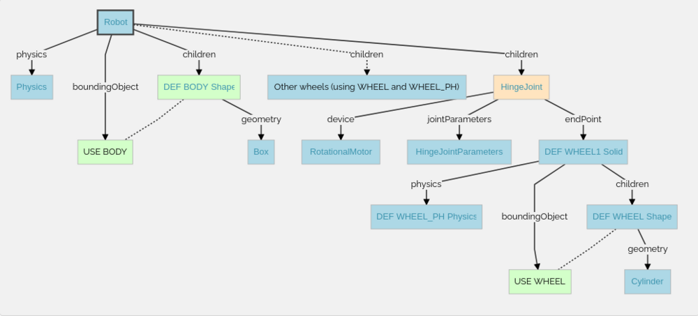
The figure above demonstrates the structure of the robot in details, how the 3D model is modeled in Weobts using the scene tree.
Representation of a HingeJoint 2.2 Format
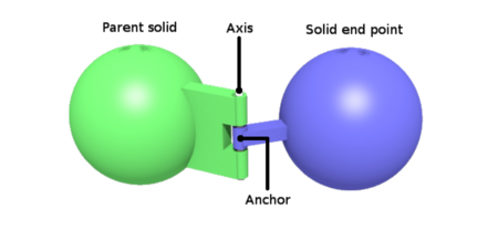
In Webots, whenever rotary or linear motion is used, we must use a HingeJoint. In our case, since we are using RotationalMotor for moving the wheels, HingeJoints are being used to anchor the wheels to the body. As we can see in the photo, Parent solid is in our case the body of the robot and wheels are attached as solid end points. In the HingeJoint node we also use RotationalMotor as a Device for moving the robot.
Sensors
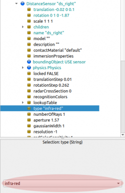
In our case, two IR sensors are used to measure distance in the beginning for the 4-Wheeled-Robot. In Webots these sensors are found as DistanceSensors. There are four type of distance sensors in Webots. They are -
- Gerneric,
- Infra-red,
- Sonar,
- Laser.
In Webots, these options can be found under the Children, inside DistanceSensor. There is an example in Figure. 8 that shows how to change between different types of Distance Sensors by selecting the 'type' field of DistanceSensor from the scene tree.
Demo-Programs
Software
Summary
Weiterführende Links
→ zurück zum Hauptartikel: Praxissemester Projektteam WS2021