AlphaBot Linienverfolgungsssensor: Unterschied zwischen den Versionen
Keine Bearbeitungszusammenfassung |
|||
| Zeile 129: | Zeile 129: | ||
{{#ev:youtube|https://youtu.be/8ZPffd-RMfk| 500 | | Robotics Alpha-Bot Course by TESR(Line Tracking)|frame}} | {{#ev:youtube|https://youtu.be/8ZPffd-RMfk| 500 | | Robotics Alpha-Bot Course by TESR(Line Tracking)|frame}} | ||
= Gleichzeitige Verwendung von Ultraschallsensor und Linetracker= | |||
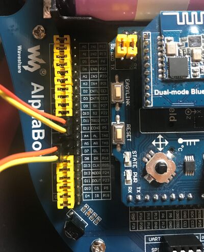
Bei gleichzeitiger Verwendung des Ultraschallsensors und des Linienverfolgers wie z.B. für Aufgabe 3.4 im Praktikum müssen die Pins mit Jumper Kabeln neu verbunden werden. In der Folgenden Abbildung ist diese Verkabelung einmal abgebildet. | |||
[[Datei:JumperWire AlphaBot.JPG|thumb|center|400px|Jumper Kabel bei gleichzeitiger Verwendung von Ultraschallsensor und Linetracker]] | |||
Version vom 11. Mai 2021, 15:54 Uhr

Autoren: Prof. Dr.-Ing. Schneider
Einleitung
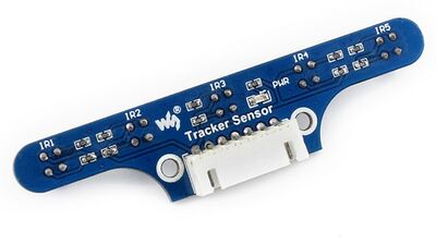
Infrarot Linienverfolgungssensor für den AlphaBot
Getting Started
Prinzip des Linienverfolgers
Der Linienverfolgungssensor besteht aus 5 Analogsensoren. Die Messdaten hängen von der Distanz und der Farbe des detektierten Objektes ab. Ein Objekt mit höherer Infrarotreflektanz (z. B. Weiß) wird einen höheren Ausgangswert liefern. Ein Objekt mit geringer IR.reflektanz (z. B. Schwarz) wird eine geringe Analogausgabe liefern. Nähert sich ein Sensor der Farbe Schwarz, wird der Messwert kleiner und kleiner. Aus diesem Verhalten lässt sich auf die Distanz zur schwarzen Linie schließen. Je näher der Sensor der schwarzen Linie ist, desto kleiner ist der Ausgabewert. Im Vergleich zu anderen Modulen, die nur logische Signale (HIGH/LOW) ausgeben, ist so eine präzisere Regelung möglich. nachfolgend wird der Algorithmus in 3 Teilen präsentiert.
Teil 1: Kalibrierung
Verschiedene Sensoren können verschiedene Werte für dieselbe Farbe und Distanz ausgeben. Zusätzlich kann das Umgebunggslicht den Analogwert beeinflussen. Wid ein Analogwert mit 10 Bit A/D gewandelt, ist ein theoretischer Wertebereich von 0 bis 1023 möglich. In Realität wird der minimal messbare Wert über Null und der maximal messbare Wert unter 1023 liegen. Eine Kalibrierung bzw. Normalisierung um die verschiedenen Sensor- und Umweldfaktoren zu reduzieren. Beim Normalisierungsprozess handelt es sich um eine lineare Transformation indem der Messbereich Min~Max mit der nachfolgenden Formel auf 0-1 transformiert wird.
Dabei ist x der orginale Ausgabewert des Sensors und y der transformierte Wert. Max und Min sind die maximalen und (In which, x is the original output value from sensor, y is the transformed value, and Max and Min are the maximum output value and the minimum output value, respectively.
y = (x - Min) * 1000 / (Max - Min)
After transformed, the output value will be in the range of 0~1000, in which 1000 means the sensor is far away from the black line, and 0 means the sensor is above the black line.
The program will sample the values from the sensors for many times to get the proper value of Min and Max. In order to get the precise Min and Max, the car should be always running in course of sampling. Part 2: Weighted average
Using normalization process to deal with five sets of output data, we will get five sets of data about the distances between the sensors and the black line. Then, we should use weighted average to transform these data into a value to determine center line of the route with the following formula:
y = (0 * value0 + 1000 * value1 + 2000 * value2 + 3000 * value3 +4000 * value4) / (value0 + value1 + value2 + value3 + value4)
In which, 0, 1000, 2000, 3000, 4000 are the weights for the five detectors, respectively, from left to right. And value0~value4 are the data with normalization process.
Now, we can get the data in the range of 0~4000, which can tell you the position of the black line. For example, 2000 means the black line is in the middle of the module, 0 means the black line is on the leftmost side of the module, and 4000 means the black line is on the rightmost side of the module.
For more precise detection, we have some requirements on the height of the module and the width of the black line. The width of the black line should be equal to or less than the distance of two sensors (16mm). The proper height of the module is that when the black line is in the middle of two sensors, both sensors can detect the black line. Part 3: PID control
From Part 2, we can get the position of the black line. You should make sure the black line is always under the car, so that the car can run along the black line. So, the output value after weight average process should be kept at 2000. Here, we employ positional PID control to make the car run smoothly. About the PID algorithm, you can easy get a lot of information via Internet. In here, we only have a brief description on it.
PID control can feedback and regulate the error with three factors, proportional (P), Integral (I), derivative (D). The followings are PID algorithm.
proportional = position - 2000; derivative = proportional - last_proportional; integral += proportional;
last_proportional = proportional;
power_error = proportional * Kp + integral * Ki + derivative * Kd;
in which:
Ideally, the weighted average output is 2000, that is, the black line is kept in the middle. The proportional is the result of current position(Position) minus objective position (2000). It is the position error, of which the positive number means the car is on the right of the black line, and the negative number means the car is on the left of the black line.
Integral is the sum of all the errors. When the absolution value is large, the error accumulation is large too, which means the car go far away from the route.
Derivative is the difference of the current proportional and the last proportional, reflecting the response speed of the car. The large derivative value means the fast response speed.
You can adjust the parameters Kp, Ki and kd to have the better performance. Firstly, we adjust Kp; set the Ki and Kd to 0, and adjust the value of Kp to make the car run along the black line. Then, adjust Ki and Kd; set the parameters to a small value or 0. AlphaBot tracker module example explanation
In this section, we will present the Tracker Sensor program of the AlphaBot smart car. Here, we will take the Arduino program as example. There are two main files in the Tracker Sensor library, TRSensors.cpp and TRSensors.h.
TRSensors.cpp contains the following functions:
TRSensors(); void AnalogRead(unsigned int *sensor_values); void calibrate(); void readCalibrated(unsigned int *sensor_values); int readLine(unsigned int *sensor_values, unsigned char white_line = 0);
in which, TRSensors() is the initial function for pins initialization. And it has been applied for the memory space to store the Max and Min values of the sensors.
AnalogRead() function can read the analog value from 5 channel of sensors. And AlphaBot performs AD conversation via the AD chip of TLC1543, but not the AD pins on the Arduino chip. When you connect the Trackr Sensor to the Pins A0 ~A4 of the Arduino chip, you should modify this function.
calibrate() function is used for calibration, determining the values of Max and Min by sampling the data for many times. In calibration, the car should run along the black line and swing from side to side, to get the precise value of Max and Min
readCalibrated() is for normalization process. From Part 1, we can know that it can transform the output data to the range of 0~1000 by linear transformation, in which 1000 means the sensor is far away from the black line, and 0 means the sensor is above the black line.
readLine() can read the position of the black line. For more detailed information, please refer to Part 2. This function applies weight average to calculate the position of the black line. Then you can get the data in the range of 0~4000, in which 0 means the black line is on the leftmost side of the module, and 4000 means the black line is on the rightmost side of the module.
PID control is implemented in the main function Infrared_Line_Tracking.ino. The following is the relative Demo code.
In this Demo code, we use the function readline() to read the position of the black line, and calculate the proportional and the derivative. Here is PD algorithm not PID algorithm, so there is no integral. If you want a better performance, you can modify the parameters in the PD algorithm.
At last, we use PID algorithm to calculate the iterm power_error, so as to adjust the PWM of the right and the left wheels to make the car run along the black line. Operation and phenomena
In this section, we only introduce the simple test program of the module. For more information about how to apply AlphaBot to use Tracker Sensor to implement tracking operation and relative Demo, please refer to the corresponding documents of AlphaBot.
Here we will illustrate how to use the peripherals with the development board XNUCLEO-F103RB (STM32F103RB) and UNO PLUS.
① Download the corresponding program into the development board.
② Connect the module to the development board, and connect your PC to the board via a serial cable. Then, start the serial debugging software.
Table 1 and Table 2 show the connection between the module and the development boards. Port Pins of XNUCLEO-F103RB IR1~IR5 A0~A4 GND GND VCC 3.3V
Table 1 Connection between the module and STM32 Port Pins of Arduino IIR1~IR5 A0~A4 IGND GND IVCC 5V
Table 2 Connection between the module and Arduino
Table 3 shows the serial port configuration. Baud rate 9600 Data bits 8 Stop bit 1 Parity bit None
Table 3 Serial port configuration
③ The screen will display 5 serial of data for IR1 to IR 5 sensors. All this data will change with the reflective distance. When there is no obstacle in front of the module, the output is probably a few dozen, but when the module is close to the table, its output will go up to about 800~900. Resources
Hinweis
Beachten Sie die Kalibrierung! Zuerst auf einen hellen und dann einem dunklen Untergrund stellen. Anschließend folgt der Roboter dem dunklen Wert.
Video der Inbetriebnahme
Gleichzeitige Verwendung von Ultraschallsensor und Linetracker
Bei gleichzeitiger Verwendung des Ultraschallsensors und des Linienverfolgers wie z.B. für Aufgabe 3.4 im Praktikum müssen die Pins mit Jumper Kabeln neu verbunden werden. In der Folgenden Abbildung ist diese Verkabelung einmal abgebildet.

Weiterführende Links
→ zurück zum Hauptartikel: AlphaBot Bauanleitung