Camera Calibration Toolbox: Unterschied zwischen den Versionen
Zur Navigation springen
Zur Suche springen
Keine Bearbeitungszusammenfassung |
|||
| Zeile 53: | Zeile 53: | ||
\Psi\\ | \Psi\\ | ||
\end{pmatrix}=\begin{pmatrix} | \end{pmatrix}=\begin{pmatrix} | ||
100,5\\ | |||
1,4\\ | |||
-0 | -0,5\\ | ||
\end{pmatrix}</math> | \end{pmatrix}deg</math> | ||
Der Translationsvektor <math>\vec{T}</math> | Der Translationsvektor <math>\vec{T}</math> | ||
<math>T=\begin{pmatrix} | |||
t_{x}\\ | |||
t_{y}\\ | |||
t_{z}\\ | |||
\end{pmatrix}=\begin{pmatrix} | |||
-452.4129\\ | |||
129.9002\\ | |||
726.9537\\ | |||
\end{pmatrix}</math> | |||
Version vom 18. Mai 2014, 11:43 Uhr
Autor:
Dieser Artikel beschreibt die Arbeit mit der Camera Calibration Toolbox for Matlab von Jean-Yves Bouguet.
Matlab 2014a beinhaltet eine ähnliche Toolbox, aber bei diese Variante hat man die Möglichkeit den Quelltext nachzuvollziehen.
Installation
- Download der Toolbox
- Einbindung der Toolbox mit
Set Path. - Start der Toolbox mit
calib_gui.
Berechnung extrinsischer Parameter
- Der Knopf
Comp. Extrinsicder GUI ruftextrinsic_computation.mauf. - Laden Sie die Kameraparameter Calib_Results.mat oder Kalibrieren Sie Ihre Kamera
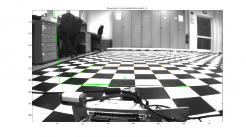
- Sie werden aufgefordert die verzerrte Bilddatei zu laden.
Image name (full name without extension): VRmDC_Boden1
Image format: ([]='r'='ras', 'b'='bmp', 't'='tif', 'p'='pgm', 'j'='jpg', 'm'='ppm') t

Extraction of the grid corners on the image
Window size for corner finder (wintx and winty):
wintx ([] = 5) = 5
winty ([] = 5) = 5
Window size = 11x11
Click on the four extreme corners of the rectangular complete pattern (the first clicked corner is the origin)...
Could not count the number of squares in the grid. Enter manually.
Number of squares along the X direction ([]=10) = 5
Number of squares along the Y direction ([]=10) = 5
Size dX of each square along the X direction ([]=30mm) = 16.6
Size dY of each square along the Y direction ([]=30mm) = 16.6
Corner extraction...
Das errechnete Ergebnis lautet
Extrinsic parameters:

Translation vector: Tc_ext = [ -46.048515 	 13.733091 	 72.490486 ]
Rotation vector:   omc_ext = [ 1.753991 	 0.023825 	 -0.007702 ]
Rotation matrix:    Rc_ext = [ 0.999759 	 0.020374 	 0.008164
                               0.011740 	 -0.182129 	 -0.983205
                               -0.018545 	 0.983063 	 -0.182325 ]
Pixel error:           err = [ 0.42985 	 0.54546 ]
Der Rotationsvektor in deg beträgt
Der Translationsvektor
