AlphaBot: Steckbrücken: Unterschied zwischen den Versionen
Zur Navigation springen
Zur Suche springen
Keine Bearbeitungszusammenfassung |
Keine Bearbeitungszusammenfassung |
||
| Zeile 13: | Zeile 13: | ||
|A || Motoren | |A || Motoren | ||
|- | |- | ||
|B || [[AlphaBot_Lichtschranke| Lichtschranke für | |B || [[AlphaBot_Lichtschranke| Lichtschranke für Radodometrie]] | ||
|- | |- | ||
|C || [[Servomotor_SG90|Servomotor]] | |C || [[Servomotor_SG90|Servomotor]] | ||
| Zeile 79: | Zeile 79: | ||
|+ style = "text-align: left"|Tabelle 4: Digital-Pinbelegung des [[AlphaBot_Uno_Plus|AlphaBot Uno Plus]] | |+ style = "text-align: left"|Tabelle 4: Digital-Pinbelegung des [[AlphaBot_Uno_Plus|AlphaBot Uno Plus]] | ||
|- | |- | ||
! IO !! A !! B !! C !! D !! E !! F !! G !! XBee!! OLED!!RGB-LED | ! IO !! A !! B !! C !! D !! E !! F !! G !! XBee!! OLED!!RGB-LED!!ACC!!Piezo | ||
|- | |- | ||
|D0 || || || || || || || || || || || | |D0 || || || || || || || || || || || || | ||
|- | |- | ||
|D1 || || || || || || || ||x | |D1 || || || || || || || ||x || || || || | ||
|- | |- | ||
|D2 || ||x || || || || || ||x | |D2 || ||x || || || || || ||x || || || || | ||
|- | |- | ||
|D3 || ||x | |D3 || ||x || || || || || || || || || || | ||
|- | |- | ||
|D4 || || || || || || ||x | |D4 || || || || || || ||x || || || || || | ||
|- | |- | ||
|D5 ||x | |D5 ||x|| || || || || || || || || || || | ||
|- | |- | ||
|D6 ||x | |D6 ||x|| || || || || || || || || || || | ||
|- | |- | ||
|D7 || || || || ||x|| || || ||x | |D7 || || || || ||x|| || || ||x || || || | ||
|- | |- | ||
|D8 || || || || ||x || || || ||x | |D8 || || || || ||x || || || ||x || || || | ||
|- | |- | ||
|D9 || || ||x || || || || ||x | |D9 || || ||x || || || || ||x || || || || | ||
|- | |- | ||
|D10 || || ||x || || ||x || ||x | |D10 || || ||x || || ||x || ||x || || || || | ||
|- | |- | ||
|D11 || || || ||x || ||x || || || || || | |D11 || || || ||x || ||x || || || || || ||x | ||
|- | |- | ||
|D12 || || || ||x || ||x || || || || || | |D12 || || || ||x || ||x || || || || || || | ||
|- | |- | ||
|D13 || || || || || ||x || || || || || | |D13 || || || || || ||x || || || || || || | ||
|- | |- | ||
|} | |} | ||
Version vom 11. April 2023, 13:22 Uhr

Autoren: Prof. Dr.-Ing. Schneider
Einleitung
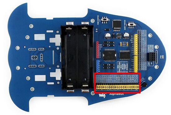
Über die in Abb. 1 markierten Steckbrücken werden die Sensoren und Aktoren des AlphaBot mit dem AlphaBot Uno Plus verbunden.
| Gruppe | Sensoren/Aktoren |
|---|---|
| A | Motoren |
| B | Lichtschranke für Radodometrie |
| C | Servomotor |
| D | Ultraschallsensor |
| E | Infrarot-Abstandssensoren |
| F | Linienverfolgungsssensor |
| G | IR Empfänger |
Doppelung bei der Pinbelegung betrifft vorwiegend die Multisensorerweiterung (Accessory Shield). Die Multisensorerweiterung verfügt über die in Tabelle 2 dargestellten Sensoren.
| # | Sensoren | IO-Pins |
|---|---|---|
| 1 | XBee-Modul | D1, D2, D9, D10 |
| 2 | OLED-Display | I²C-Addresse: 0x3C/0x3D, SCL, SDA, D7, D8 |
| 3 | RGB-LED | D5, D6, D12 |
| 4 | Joystick | A1, A2, A3, A4, A5 |
| 5 | Temperatursensor LM75B | I²C-Addresse: 0x48, SCL, SDA |
| 6 | Potentiometer | A0 |
| 7 | I²C Real-Time-Clock (RTC) | |
| 8 | Real-Time-Clock (RTC) | I²C-Addresse: 0x68, SCL, SDA |
| 9 | Piezo-Lautsprecher | D11 |
| IO | A | B | C | D | E | F | G | Poti | Joystick |
|---|---|---|---|---|---|---|---|---|---|
| A0 | x | x | |||||||
| A1 | x | x | |||||||
| A2 | x | x | |||||||
| A3 | x | x | |||||||
| A4 | x | x | |||||||
| A5 | x | x | |||||||
| A6 | |||||||||
| A7 |
| IO | A | B | C | D | E | F | G | XBee | OLED | RGB-LED | ACC | Piezo |
|---|---|---|---|---|---|---|---|---|---|---|---|---|
| D0 | ||||||||||||
| D1 | x | |||||||||||
| D2 | x | x | ||||||||||
| D3 | x | |||||||||||
| D4 | x | |||||||||||
| D5 | x | |||||||||||
| D6 | x | |||||||||||
| D7 | x | x | ||||||||||
| D8 | x | x | ||||||||||
| D9 | x | x | ||||||||||
| D10 | x | x | x | |||||||||
| D11 | x | x | x | |||||||||
| D12 | x | x | ||||||||||
| D13 | x |
→ zurück zum Hauptartikel: AlphaBot