AlphaBot Uno Plus: Unterschied zwischen den Versionen
Zur Navigation springen
Zur Suche springen
| Zeile 24: | Zeile 24: | ||
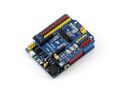
| <big><big>①</big></big> || ATMEGA328P-AU|| | | <big><big>①</big></big> || ATMEGA328P-AU|| | ||
|- | |- | ||
| <big><big>②</big></big> || | | <big><big>②</big></big> || AMS1117-3.3|| 3,3 V Spannungsregler | ||
|- | |- | ||
| <big><big>③</big></big> || || | | <big><big>③</big></big> || NCP1117ST50T3G|| 5 V Spannungsregler | ||
|- | |- | ||
| <big><big>④</big></big> || || | | <big><big>④</big></big> || FT232RL|| USB zu UART Anschluss | ||
|- | |- | ||
| <big><big>⑤</big></big> || || | | <big><big>⑤</big></big> || Arduino Interface|| kompatibel mit dem standard Arduino Interface, zusätzliche Analogeingänge A6 (CFG), A7 | ||
|- | |- | ||
| <big><big>⑥</big></big> || || | | <big><big>⑥</big></big> || ICSP Interface|| | ||
|- | |- | ||
| <big><big>⑦</big></big> || || | | <big><big>⑦</big></big> || MICRO USB Anschluss || Serielle Verbindung zum PC | ||
|- | |- | ||
| <big><big>⑧</big></big> || || | | <big><big>⑧</big></big> || Spannungsausgang || 3,3 V oder 5 V, voltage level configured by the onboard power configuration switch, used as power output OR common-grounding with other boards | ||
|- | |- | ||
| <big><big>⑨</big></big> || || | | <big><big>⑨</big></big> || FT232 || Prorammierung des Bootloaders für dem µC | ||
|- | |- | ||
| <big><big>⑩</big></big> || || | | <big><big>⑩</big></big> || DC Eingang||7 V ~ 12 V | ||
|- | |- | ||
| <big><big>⑪</big></big> || || | | <big><big>⑪</big></big> || Reset|| | ||
|- | |- | ||
| <big><big>⑫</big></big> || || | | <big><big>⑫</big></big> || Spannungsanzeige LED|| | ||
|- | |- | ||
| <big><big>⑬</big></big> || || | | <big><big>⑬</big></big> || Serielle Anzeige LEDs Rx/Tx|| | ||
|- | |- | ||
| <big><big>⑭</big></big> || || | | <big><big>⑭</big></big> || User LED|| | ||
|- | |- | ||
| <big><big>⑮</big></big> || || | | <big><big>⑮</big></big> || 500 mA selbstheilende Sicherung|| | ||
|- | |- | ||
| <big><big>⑯</big></big> || || | | <big><big>⑯</big></big> || Spannungskonfigurator|| | ||
|- | |- | ||
| <big><big>⑰</big></big> || || | | <big><big>⑰</big></big> || Bootloader Auswahlschalter || ON : the board will reset when power-up OR other USB devices were detected connecting to the PC<br> | ||
OFF : the onboard program runs immediately when power-up, and the board will not reset when other USB devices were detected connecting to the PC | |||
|- | |- | ||
|} | |} | ||
Version vom 29. März 2023, 14:52 Uhr

Autoren: Prof. Dr.-Ing. Schneider
Einleitung
Der UNO PLUS ist ein Entwiclungsboard, welches mit dem Arduino UNO R3 kompatibel ist.
Vergleich UNO PLUS vs. UNO R3
| UNO PLUS | UNO R3 | Bemerkung | |
|---|---|---|---|
| Betriebsspannung | 5V/3.3V | 5V | Zwei Spannungspegel zur Unterstützung div. Erweiterungen |
| Betriebsspannung |
Bestückung des UNO PLUS

| Bauteil | Bemerkung | |
|---|---|---|
| ① | ATMEGA328P-AU | |
| ② | AMS1117-3.3 | 3,3 V Spannungsregler |
| ③ | NCP1117ST50T3G | 5 V Spannungsregler |
| ④ | FT232RL | USB zu UART Anschluss |
| ⑤ | Arduino Interface | kompatibel mit dem standard Arduino Interface, zusätzliche Analogeingänge A6 (CFG), A7 |
| ⑥ | ICSP Interface | |
| ⑦ | MICRO USB Anschluss | Serielle Verbindung zum PC |
| ⑧ | Spannungsausgang | 3,3 V oder 5 V, voltage level configured by the onboard power configuration switch, used as power output OR common-grounding with other boards |
| ⑨ | FT232 | Prorammierung des Bootloaders für dem µC |
| ⑩ | DC Eingang | 7 V ~ 12 V |
| ⑪ | Reset | |
| ⑫ | Spannungsanzeige LED | |
| ⑬ | Serielle Anzeige LEDs Rx/Tx | |
| ⑭ | User LED | |
| ⑮ | 500 mA selbstheilende Sicherung | |
| ⑯ | Spannungskonfigurator | |
| ⑰ | Bootloader Auswahlschalter | ON : the board will reset when power-up OR other USB devices were detected connecting to the PCOFF : the onboard program runs immediately when power-up, and the board will not reset when other USB devices were detected connecting to the PC |
UNO PLUS Fotos
- Installationsabläufe als Slideshow
-
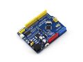 Oberseite
 -
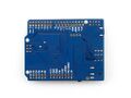 Unterseite
 -
 UNO PLUS mit Motorplatine
 -
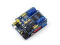
 UNO PLUS mit IO Erweiterung
 -
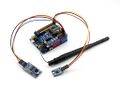 UNO PLUS mit Wifi Erweiterung und Sensoren
 -
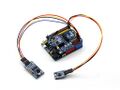 UNO PLUS mit XBee Erweiterung und Sensoren
 -
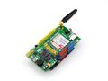 UNO PLUS mit GPS/GSM Erweiterung


Download
Weiterführende Links
→ zurück zum Hauptartikel: AlphaBot Bauanleitung