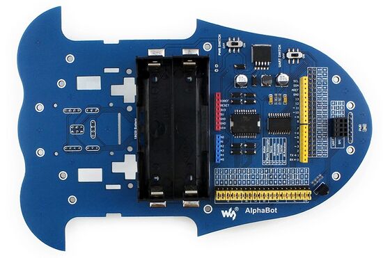
AlphaBot Hauptplatine: Unterschied zwischen den Versionen
Zur Navigation springen
Zur Suche springen
Keine Bearbeitungszusammenfassung |
Keine Bearbeitungszusammenfassung |
||
| Zeile 2: | Zeile 2: | ||
[[Datei:AlphaBot-1.jpg|thumb|rigth|550px|Abb. 1: AlphaBot Hauptplatine]] | [[Datei:AlphaBot-1.jpg|thumb|rigth|550px|Abb. 1: AlphaBot Hauptplatine]] | ||
'''Autoren:''' [[Benutzer:Ulrich_Schneider| Prof. Dr.-Ing. Schneider]] | '''Autoren:''' [[Benutzer:Ulrich_Schneider| Prof. Dr.-Ing. Schneider]] | ||
== Übersicht == | |||
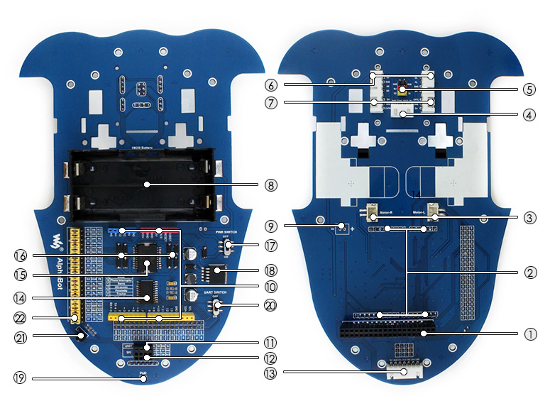
[[Datei:AlphaBot-intro.jpg|ohne|900px|Abb. 2: Übersicht der Hauptplatine]] | |||
Raspberry Pi interface: for connecting Raspberry Pi | |||
Arduino interface: for connecting Arduino | |||
Motor interface | |||
Ultrasonic module interface | |||
Servo module interface | |||
Obstacle avoidance module interface | |||
Speed measuring interface | |||
Battery holder: supports 18650 batteries | |||
Reserved power input (not soldered): for connecting other external power supply | |||
Arduino expansion header: for connecting Arduino shields | |||
UART interface: for connecting Bluetooth module, to control the robot remotely via Bluetooth | |||
SPI interface: for connecting NRF24L01 wireless module | |||
Line tracking module interface | |||
TLC1543: 10-bit AD acquisition chip, allows the Pi to use analog sensors | |||
L298P: dual H bridge motor driver chip, up to 2A current | |||
Anti-reverse diode | |||
Power switch | |||
LM2596: 5V regulator' | |||
Power indicator | |||
UART switch: turn on to enable serial communication between Raspberry Pi and Arduino | |||
IR receiver: control the robot remotely via infrared | |||
Raspberry Pi/Arduino selection: select the Raspberry Pi or Arduino to control the robot peripherals | |||
{| class="wikitable" | |||
|+ style = "text-align: left"|Tabelle 1: Inhalt des AlphaBot Bausatzes | |||
|- | |||
! Pos. !! Anz. !! Beschreibung !! !! Pos. !! Anz. !! Beschreibung !! | |||
|- | |||
|<big><big>①</big></big> || 1 || [[AlphaBot Hauptplatine|AlphaBot Hauptplatine]] || [[Datei:AlphaBot-1.jpg|ohne|100px|]] ||<big><big>⑬</big></big> || 2 || XH2.54, 4cm, vieradrig ||[[Datei:XH2.54-wire-4cm-4PINx2PCS.jpg|ohne|100px|]] | |||
|- | |||
|<big><big>②</big></big> || 1 || [[AlphaBot Linienverfolgungsssensor|Linienverfolgungsssensor]] || [[Datei:Tracker-Sensor-1.jpg|ohne|100px|]]||<big><big>⑭</big></big> || 1 || XH2.54, 4cm, siebenadrig ||[[Datei:XH2.54-wire-4cm-7PIN.jpg|ohne|100px|]] | |||
|- | |||
|<big><big>③</big></big> || 2 || [[AlphaBot Lichtschranke|Lichtschranke für Radodometrie]]|| [[Datei:Photo-Interrupter-Sensor-1.jpg|ohne|100px|]]|| <big><big>⑮</big></big> || 1 || Schraubensatz (vgl. Tabelle 2) || [[Datei:Bauanleitung 01.jpg|ohne|100px|]] | |||
|- | |||
|<big><big>④</big></big> || 2 || [[AlphaBot Infrarot-Abstandssensor|Infrarot-Abstandssensor]]||[[Datei:Infrared-Proximity-Sensor-1.jpg|ohne|100px|]] || <big><big>⑯</big></big> || 1 || [[AlphaBot Uno Plus|Arduino Uno R3 PLUS]]||[[Datei:R3-PLUS-1.jpg|ohne|100px|]] | |||
|- | |||
|<big><big>⑤</big></big> || 2 || Motor mit Getriebe|| [[Datei:Yellow-Motor.jpg|ohne|100px|]]|| <big><big>⑰</big></big> ||1||[[AlphaBot Multisensor-Shield|Multisensor-Shield]]||[[Datei:Accessory-Shield-1.jpg|ohne|100px|]] | |||
|- | |||
|<big><big>⑥</big></big> || 2 || Gummirad || [[Datei:Rubber-Wheel.jpg|ohne|100px|]]||<big> <big>⑱</big></big>||1||[[AlphaBot Bluetooth Modul|Bluetooth Modul]] || [[Datei:Dual-mode-Bluetooth-1.jpg|ohne|100px|]] | |||
|- | |||
|<big><big>⑦</big></big> || 1 || Akryl Bodenplatte|| [[Datei:AlphaBot-Case.jpg|ohne|100px|]]|| <big><big>⑲</big></big>||1||[[Ultraschallsensor HC-SR04]]|| [[Datei:Ultrasonic-Sensor-1.jpg|ohne|100px|]] | |||
|- | |||
|<big><big>⑧</big></big> || 4 || Halteklammern für die Motoren||[[Datei:Motor-Holder.jpg|ohne|100px|]] ||<big><big>⑳</big></big>|| 1||[[Servomotor SG90]] || [[Datei:SG90.jpg|ohne|100px|]] | |||
|- | |||
|<big><big>⑨</big> || 1 || Allseitenrad|| [[Datei:Universal-Wheel.jpg|ohne|100px|]]||<big>㉑</big>||1||Ultraschall-Adapterplatine||[[Datei:Ultrasonic-Adapter.jpg|ohne|100px|]] | |||
|- | |||
|<big><big>⑩</big></big> || 1 || Radencoder-Scheiben mit 20 Schlitzen||[[Datei:Encoding-disk-2PCS.jpg|ohne|100px|]] ||<big>㉒</big>||1||Montagerahmen für den Servomotor||[[Datei:Steering-gear-holder.jpg|ohne|100px|]] | |||
|- | |||
|<big><big>⑪</big></big> || 1 || IR-Fernbedienung||[[Datei:Infrared-Remote-Controller.jpg|ohne|100px|]] ||<big>㉓</big>||1||XH2.54, 20cm, vieradrig||[[Datei:XH2.54-wire-20cm-4PIN.jpg|ohne|100px|]] | |||
|- | |||
|<big><big>⑫</big></big> || 2 || XH2.54, 4cm, dreiadrig||[[Datei:XH2.54-wire-4cm-3PINx2PCS.jpg|ohne|100px|]]|| <big>㉔</big>||1|| USB Kabel (Typ A zu Micro-B)||[[Datei:USB-type-A-plug-to-Micro-B-plug-cable.jpg|ohne|100px|]] | |||
|- | |||
|} | |||
== Weiterführende Links == | == Weiterführende Links == | ||
Version vom 5. März 2021, 18:52 Uhr

Autoren: Prof. Dr.-Ing. Schneider
Übersicht

   Raspberry Pi interface: for connecting Raspberry Pi
   Arduino interface: for connecting Arduino
   Motor interface
   Ultrasonic module interface
   Servo module interface
   Obstacle avoidance module interface
   Speed measuring interface
   Battery holder: supports 18650 batteries
   Reserved power input (not soldered): for connecting other external power supply
   Arduino expansion header: for connecting Arduino shields
   UART interface: for connecting Bluetooth module, to control the robot remotely via Bluetooth
   SPI interface: for connecting NRF24L01 wireless module
   Line tracking module interface
   TLC1543: 10-bit AD acquisition chip, allows the Pi to use analog sensors
   L298P: dual H bridge motor driver chip, up to 2A current
   Anti-reverse diode
   Power switch
   LM2596: 5V regulator'
   Power indicator
   UART switch: turn on to enable serial communication between Raspberry Pi and Arduino
   IR receiver: control the robot remotely via infrared
   Raspberry Pi/Arduino selection: select the Raspberry Pi or Arduino to control the robot peripherals
| Pos. | Anz. | Beschreibung | Pos. | Anz. | Beschreibung | ||
|---|---|---|---|---|---|---|---|
| ① | 1 | AlphaBot Hauptplatine |  |
⑬ | 2 | XH2.54, 4cm, vieradrig |  |
| ② | 1 | Linienverfolgungsssensor | ⑭ | 1 | XH2.54, 4cm, siebenadrig |  | |
| ③ | 2 | Lichtschranke für Radodometrie |  |
⑮ | 1 | Schraubensatz (vgl. Tabelle 2) |  |
| ④ | 2 | Infrarot-Abstandssensor |  |
⑯ | 1 | Arduino Uno R3 PLUS |  |
| ⑤ | 2 | Motor mit Getriebe |  |
⑰ | 1 | Multisensor-Shield |  |
| ⑥ | 2 | Gummirad |  |
⑱ | 1 | Bluetooth Modul |  |
| ⑦ | 1 | Akryl Bodenplatte |  |
⑲ | 1 | Ultraschallsensor HC-SR04 |  |
| ⑧ | 4 | Halteklammern für die Motoren |  |
⑳ | 1 | Servomotor SG90 |  |
| ⑨ | 1 | Allseitenrad |  |
㉑ | 1 | Ultraschall-Adapterplatine |  |
| ⑩ | 1 | Radencoder-Scheiben mit 20 Schlitzen |  |
㉒ | 1 | Montagerahmen für den Servomotor |  |
| ⑪ | 1 | IR-Fernbedienung |  |
㉓ | 1 | XH2.54, 20cm, vieradrig |  |
| ⑫ | 2 | XH2.54, 4cm, dreiadrig |  |
㉔ | 1 | USB Kabel (Typ A zu Micro-B) |  |
Weiterführende Links
→ zurück zum Hauptartikel: AlphaBot Bauanleitung
