Inbetriebnahme der Pixy 2.1 mit Simulink: Unterschied zwischen den Versionen
Zur Navigation springen
Zur Suche springen
Keine Bearbeitungszusammenfassung |
|||
| (37 dazwischenliegende Versionen desselben Benutzers werden nicht angezeigt) | |||
| Zeile 6: | Zeile 6: | ||
|} | |} | ||
= Software Vorbereitung = | |||
Installieren Sie folgende Software | |||
* Simulink Coder | |||
* Simulink Support Package for Arduino Hardware | |||
* PixyMon v2 3.0.24 | |||
= Hardware Verbindung mit Originalkabel (ISCP)= | |||
[[Datei:WikiLink.png|20px]] [https://docs.pixycam.com/wiki/doku.php?id=wiki:v1:hooking_up_pixy_to_a_microcontroller_-28like_an_arduino-29 Originalartikel: Hooking up Pixy to a Microcontroller] | |||
[[Datei:Arduino ICSP.jpg|thumb|rigth|300px|Abb. 2: Verbindung Pixy 2.1 mit Flachbandkabel mit Arduino ICSP]] | |||
[[Datei:Pixy 10P.jpg|thumb|rigth|300px|Abb. 3: Verbindung Pixy 2.1 mit Flachbandkabel mit 10 poligem Stecker]] | |||
[[Datei:ArduinoR3 ICSP.jpg|thumb|rigth|300px|Abb. 4: ICSP des Arduino R3]] | |||
Steckerbelegung an der Pixy 2.1 (10P) | |||
1 2 | |||
3 4 | |||
5 6 | |||
7 8 | |||
9 10 | |||
Die Verbindung der Pixy 2 mit dem Arduino erfolgt über das mitgelieferte 6-adrige Flachbandkabel (vgl. Abb. 2 und 3). | |||
{| class="wikitable" | |||
|+ style="text-align:left;"| Tabelle 1: Verbindung des 10P ICSP Anschlusses der Pixy 2 mit dem ISCP des Arduino Uno R3 | |||
|- | |||
! Pin !! Pixy 2 !! Arduino ICSP | |||
|- | |||
| 1 || SPI MISO, UART RX, GPIO0 || SPI MISO | |||
|- | |||
| 2 || 5 V || VCC | |||
|- | |||
| 3 || SPI SCK, DAC OUT, GPIO1 || SPI SCK | |||
|- | |||
| 4 || SPI MOSI, UART TX, GPIO2 || SPI MOSI | |||
|- | |||
| 5 || I2C SCL || Reset | |||
|- | |||
| 6 || GND || GND | |||
|- | |||
| 7 || SPI SS, ADC IN, GPIO3 || | |||
|- | |||
| 8 || GND || | |||
|- | |||
| 9 || I2C SDA || | |||
|- | |||
| 10 || GND || | |||
|} | |||
'''Problem:''' SPI SS (10P) ist mit Pin 5 des Arduino ICSP '''nicht''' verbunden. | |||
{| class="wikitable" | |||
|+ style="text-align:left;"| Tabelle 2: ICSP Anschluss des Arduino Uno R3 (vgl. Abb. 4) | |||
|- | |||
! Pin !! Arduino ICSP | |||
|- | |||
| 1 || SPI MISO | |||
|- | |||
| 2 || VCC | |||
|- | |||
| 3 || SPI SCK | |||
|- | |||
| 4 || SPI MOSI | |||
|- | |||
| 5 || Reset | |||
|- | |||
| 6 || GND | |||
|} | |||
= I2C Verbindung = | |||
[[Datei:Arduino schematics pins.jpg|thumb|rigth|300px|Abb. 5: Arduino Uno R3 Pinout]] | |||
[[Datei:PixySimulink.jpg|thumb|rigth|300px|Abb. 6: Einfaches Simulink Modell]] | |||
[[Datei:PixyI2CSimulinkEinstellungen.jpg|thumb|rigth|300px|Abb. 7: Einstellungen des Simulink Pixy2-Blocks]] | |||
[[Datei:PixyMonI2CEinstellungen.jpg|thumb|rigth|300px|Abb. 8: Einstellungen des PixyMon v2 v3.0.24]] | |||
{| class="wikitable" | |||
|+ style="text-align:left;"| Tabelle 3: Handverkabelung des 10P ICSP Anschlusses der Pixy 2 mit dem Arduino Uno R3 (vgl. Abb. 5) | |||
|- | |||
! Pin !! Pixy 2 !! Arduino Uno R3 | |||
|- | |||
| 1 || SPI MISO, UART RX, GPIO0 || | |||
|- | |||
| 2 || 5 V || VCC, 5 V | |||
|- | |||
| 3 || SPI SCK, DAC OUT, GPIO1 || | |||
|- | |||
| 4 || SPI MOSI, UART TX, GPIO2 || | |||
|- | |||
| 5 || I2C SCL || SCL | |||
|- | |||
| 6 || GND || | |||
|- | |||
| 7 || SPI SS, ADC IN, GPIO3 || | |||
|- | |||
| 8 || GND || | |||
|- | |||
| 9 || I2C SDA || SDA | |||
|- | |||
| 10 || GND || GND | |||
|} | |||
== SRC == | |||
[[Datei:LineTrackingI2C R2025a.zip|Demo for Simulink R2025a]] | |||
{| role="presentation" class="wikitable mw-collapsible mw-collapsed" | |||
| <strong><code>DemoLineTrackingI2C.ino</code> </strong> | |||
|- | |||
| | |||
<syntaxhighlight lang="c" style="border: none; background-color: #EFF1C1; font-size:larger">#include <Pixy2I2C.h> | |||
Pixy2I2C pixy; // Instanz erzeugen | |||
void setup() { | |||
Serial.begin(115200); | |||
Serial.println("Serieller Monitor mit 115200 Baud gestartet..."); | |||
delay(1000); | |||
int r = pixy.init(); // Pixy2 starten (I2C automatisch) | |||
Serial.print("pixy.init(): "); | |||
Serial.println(r); | |||
Serial.println("Pixy Init ..."); | |||
delay(500); | |||
int result = -1; | |||
for (int i = 0; i < 10; i++) { // 10 Verbindungsversuche | |||
result = pixy.changeProg("line"); | |||
Serial.print("changeProg try "); | |||
Serial.print(i); | |||
Serial.print(": "); | |||
Serial.println(result); | |||
if (result >= 0) { | |||
Serial.println("Pixy2 Line Tracking gestartet..."); // Erfolgreicher Start | |||
delay(1000); | |||
break; | |||
} | |||
} | |||
} | |||
void loop() { | |||
int8_t Ergebnis_u8 = pixy.line.getMainFeatures(); | |||
if (Ergebnis_u8 <= 0) { | |||
Serial.println("Keine Linie gefunden."); | |||
delay(100); | |||
return; | |||
} | |||
// Hauptlinie (featureType = LINE_VECTOR) | |||
if (pixy.line.numVectors) { | |||
Serial.print("Linie gefunden: "); | |||
Serial.print("x0="); | |||
Serial.print(pixy.line.vectors[0].m_x0); | |||
Serial.print(" y0="); | |||
Serial.print(pixy.line.vectors[0].m_y0); | |||
Serial.print(" x1="); | |||
Serial.print(pixy.line.vectors[0].m_x1); | |||
Serial.print(" y1="); | |||
Serial.println(pixy.line.vectors[0].m_y1); | |||
} | |||
delay(50); | |||
} | |||
</syntaxhighlight> | |||
URL: https://svn.hshl.de/svn/Informatikpraktikum_1/trunk/Arduino/ArduinoLibOrdner/Pixy2/examples/DemoLineTrackingI2C/ | |||
|- | |||
|} | |||
= SPI laut MathWorks= | |||
[[Datei:Simulink Pixy2 SPI.jpg|thumb|rigth|300px|Abb. 9: Simulink Modellparameter]] | |||
[[Datei:Simulink_Pixy2_SPIwithCS.jpg|thumb|rigth|300px|Abb. 10: Einstellungen des Simulink Pixy2-Blocks SPI with CS]] | |||
[[Datei:PixyMonSPI.jpg|thumb|rigth|300px|Abb. 11: Einstellungen des PixyMon v2 v3.0.24 für SPI]] | |||
[[Datei:Kein Ergebnis Pixy2.jpg|thumb|rigth|300px|Abb. 12: Keine Daten werden angezeigt.]] | |||
{| class="wikitable" | |||
|+ style="text-align:left;"| Tabelle 2: SPI Verbindung Pixy2 10P mit Arduino Uno R3 | |||
|- | |||
! Pin !! Pixy 2.1 10P !! Arduino Uno R3 | |||
|- | |||
| 1 || SPI MISO || D12 | |||
|- | |||
| 2 || 5 V VCC || 5 V | |||
|- | |||
| 3 || SPI SCK || D13 | |||
|- | |||
| 4 || SPI MOSI || D11 | |||
|- | |||
| 6 || GND || GND | |||
|- | |||
| 7 || SPI SS || D10 | |||
|} | |||
Error: | |||
Pixy2 vision sensor supports bit order of 'MSB first' and SPI mode 3. Change the values in the 'SPI properties' of the Hardware board settings and retry. | |||
Lösung siehe Abb. 9 | |||
Folgende Einstellungen wurden getroffen | |||
* Einstellungen des Simulink Pixy2-Blocks SPI with CS siehe Abb. 10 | |||
* PixyMon siehe Abb. 11 | |||
Das Ergebnis (keine Daten) ist in Abb. 12 zu sehen. | |||
= Dokumentation = | |||
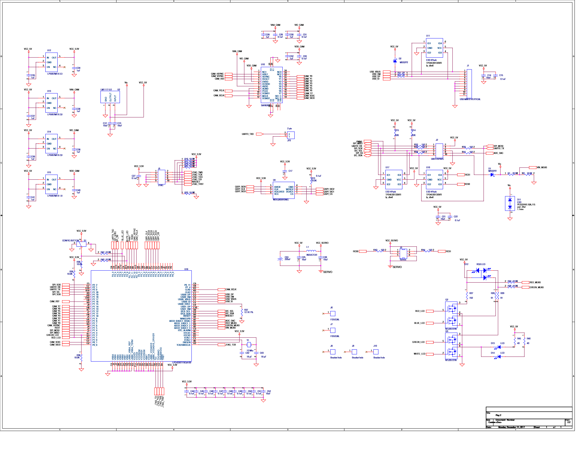
* [[medium:Pixy2 Schematic.png | Pixy 2 Schaltplan]] | |||
---- | ---- | ||
→ zurück zum Hauptartikel: [[Kamerasensor_Pixy_2.1]]<br> | → zurück zum Hauptartikel: [[Kamerasensor_Pixy_2.1]]<br> | ||
Aktuelle Version vom 2. Dezember 2025, 11:15 Uhr

| Autor: Prof. Dr.-Ing. Schneider |
Software Vorbereitung
Installieren Sie folgende Software
- Simulink Coder
- Simulink Support Package for Arduino Hardware
- PixyMon v2 3.0.24
Hardware Verbindung mit Originalkabel (ISCP)
![]() Originalartikel: Hooking up Pixy to a Microcontroller
Originalartikel: Hooking up Pixy to a Microcontroller


Steckerbelegung an der Pixy 2.1 (10P)
1  2
3  4
5  6
7  8
9  10
Die Verbindung der Pixy 2 mit dem Arduino erfolgt über das mitgelieferte 6-adrige Flachbandkabel (vgl. Abb. 2 und 3).
| Pin | Pixy 2 | Arduino ICSP |
|---|---|---|
| 1 | SPI MISO, UART RX, GPIO0 | SPI MISO |
| 2 | 5 V | VCC |
| 3 | SPI SCK, DAC OUT, GPIO1 | SPI SCK |
| 4 | SPI MOSI, UART TX, GPIO2 | SPI MOSI |
| 5 | I2C SCL | Reset |
| 6 | GND | GND |
| 7 | SPI SS, ADC IN, GPIO3 | |
| 8 | GND | |
| 9 | I2C SDA | |
| 10 | GND |
Problem: SPI SS (10P) ist mit Pin 5 des Arduino ICSP nicht verbunden.
| Pin | Arduino ICSP |
|---|---|
| 1 | SPI MISO |
| 2 | VCC |
| 3 | SPI SCK |
| 4 | SPI MOSI |
| 5 | Reset |
| 6 | GND |
I2C Verbindung


| Pin | Pixy 2 | Arduino Uno R3 |
|---|---|---|
| 1 | SPI MISO, UART RX, GPIO0 | |
| 2 | 5 V | VCC, 5 V |
| 3 | SPI SCK, DAC OUT, GPIO1 | |
| 4 | SPI MOSI, UART TX, GPIO2 | |
| 5 | I2C SCL | SCL |
| 6 | GND | |
| 7 | SPI SS, ADC IN, GPIO3 | |
| 8 | GND | |
| 9 | I2C SDA | SDA |
| 10 | GND | GND |
SRC
Datei:LineTrackingI2C R2025a.zip
DemoLineTrackingI2C.ino
|
#include <Pixy2I2C.h>

Pixy2I2C pixy; // Instanz erzeugen

void setup() {
  Serial.begin(115200);
  Serial.println("Serieller Monitor mit 115200 Baud gestartet...");
  delay(1000);

  int r = pixy.init();  // Pixy2 starten (I2C automatisch)
  Serial.print("pixy.init(): ");
  Serial.println(r);
  Serial.println("Pixy Init ...");
  delay(500);

  int result = -1;
  for (int i = 0; i < 10; i++) {      // 10 Verbindungsversuche
    result = pixy.changeProg("line");
    Serial.print("changeProg try ");
    Serial.print(i);
    Serial.print(": ");
    Serial.println(result);

    if (result >= 0) {
      Serial.println("Pixy2 Line Tracking gestartet..."); // Erfolgreicher Start
      delay(1000);
      break;
    }
  }
}
void loop() {
  int8_t Ergebnis_u8 = pixy.line.getMainFeatures();

  if (Ergebnis_u8 <= 0) {
    Serial.println("Keine Linie gefunden.");
    delay(100);
    return;
  }
  // Hauptlinie (featureType = LINE_VECTOR)
  if (pixy.line.numVectors) {
    Serial.print("Linie gefunden: ");
    Serial.print("x0=");
    Serial.print(pixy.line.vectors[0].m_x0);
    Serial.print("  y0=");
    Serial.print(pixy.line.vectors[0].m_y0);
    Serial.print("  x1=");
    Serial.print(pixy.line.vectors[0].m_x1);
    Serial.print("  y1=");
    Serial.println(pixy.line.vectors[0].m_y1);
  }
  delay(50);
}
URL: https://svn.hshl.de/svn/Informatikpraktikum_1/trunk/Arduino/ArduinoLibOrdner/Pixy2/examples/DemoLineTrackingI2C/ |
SPI laut MathWorks


| Pin | Pixy 2.1 10P | Arduino Uno R3 |
|---|---|---|
| 1 | SPI MISO | D12 |
| 2 | 5 V VCC | 5 V |
| 3 | SPI SCK | D13 |
| 4 | SPI MOSI | D11 |
| 6 | GND | GND |
| 7 | SPI SS | D10 |
Error:
Pixy2 vision sensor supports bit order of 'MSB first' and SPI mode 3. Change the values in the 'SPI properties' of the Hardware board settings and retry.
Lösung siehe Abb. 9
Folgende Einstellungen wurden getroffen
- Einstellungen des Simulink Pixy2-Blocks SPI with CS siehe Abb. 10
- PixyMon siehe Abb. 11
Das Ergebnis (keine Daten) ist in Abb. 12 zu sehen.
Dokumentation
→ zurück zum Hauptartikel: Kamerasensor_Pixy_2.1