JetRacer Bauanleitung: Unterschied zwischen den Versionen
Zur Navigation springen
Zur Suche springen
Keine Bearbeitungszusammenfassung |
|||
| (16 dazwischenliegende Versionen desselben Benutzers werden nicht angezeigt) | |||
| Zeile 5: | Zeile 5: | ||
== Einleitung == | == Einleitung == | ||
Diese Bauanleitung bezieht sich auf den Bausatz '''[https://www.waveshare.com/wiki/JetRacer_ROS_AI_Kit# JetRacer ROS AI Kit]''' des Herstellers Waveshare. | Diese Bauanleitung bezieht sich auf den Bausatz '''[https://www.waveshare.com/wiki/JetRacer_ROS_AI_Kit# JetRacer ROS AI Kit]''' des Herstellers Waveshare. | ||
== Vorbereitung der Akkus == | == Vorbereitung der Akkus == | ||
| Zeile 37: | Zeile 35: | ||
== Vorbereitung vor der Montage == | == Vorbereitung vor der Montage == | ||
* '''Austesten des Expansion Bords und Servos''' | |||
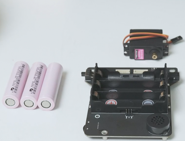
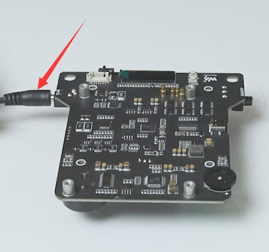
# AUSTESTEN DES NANO MODULS | **Bauen sie die Batterien in das sogennante "Expansion Board" ein, schließen sie das Aufladekabel an und aktivieren sie den Batterieschutz. | ||
[[Datei:JetRacer_Expansion_Test_Step01.png|Step01]] | |||
[[Datei:JetRacer_Expansion_Test_Step02.png|Step02]] | |||
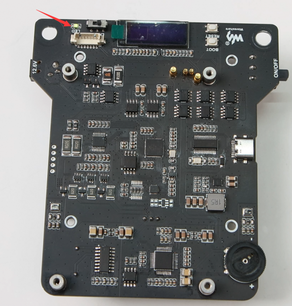
**Nachdem die Batterie erfolgreich aktivitert wurde kann die Platine mit dem An/Aus-Schalter eingeschaltet werden. Die LED auf dem Board sollte dann aufblinken. | |||
[[Datei:JetRacer_Expansion_Test_Step03.png|Step03]] | |||
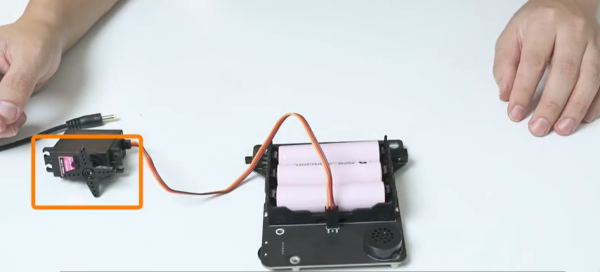
**Danach müssen sie den Servo an das Board anschließen. Dabei wird der Servo um 90° rotieren und so in deiner mittleren Position landen. <span style="color:red">Die Kabel Anordnung des Servos lautet: Gelb-PWM, Rot-5V und Braun-GND.</span> | |||
[[Datei:JetRacer_Expansion_Test_Step04.png|Step04]] | |||
# '''AUSTESTEN DES NANO MODULS''' | |||
**Quelle:[[https://developer.nvidia.com/embedded/learn/get-started-jetson-nano-devkit# get Started jetson nano devkit]] | |||
== Benötigte Werkzeuge == | == Benötigte Werkzeuge == | ||
| Zeile 47: | Zeile 54: | ||
!Pos. !! Anwendung | !Pos. !! Anwendung | ||
|- | |- | ||
|1 || | |1 || Kleine und Große Schraubendreher | ||
|- | |- | ||
|2 || Feile | |||
|} | |} | ||
== '''Teil 1: Zusammenbau Motor & Hinterräder''' == | == '''Teil 1: Zusammenbau Motor & Hinterräder''' == | ||
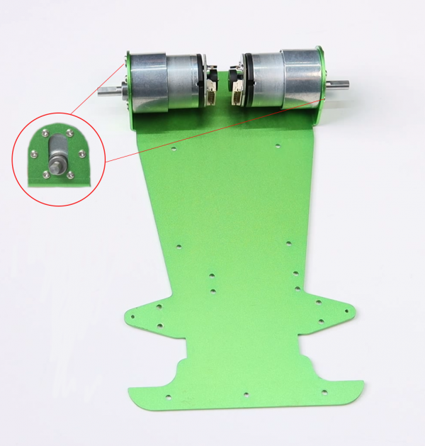
*Nutzen sie die M3*6 Schrauben um den Motor an der Metal Karosserie zu befestigen. Hier auf keinen Fall die langen Schrauben nutzen, da sonst der Motor nicht normal rotieren kann. | |||
[[Datei:JetRacer_Motor_Hinterraeder_Step01.png|Step01]] | [[Datei:JetRacer_Motor_Hinterraeder_Step01.png|Step01]] | ||
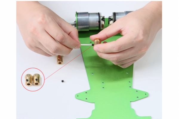
*Fixieren sie die Koppler-Schrauben auf dem Koppler mit dem passenden Schlüssel. | |||
[[Datei:JetRacer_Motor_Hinterraeder_Step02.png|Step02]] | [[Datei:JetRacer_Motor_Hinterraeder_Step02.png|Step02]] | ||
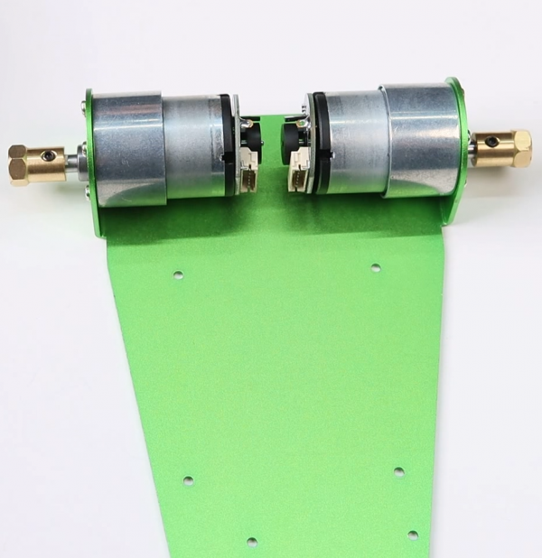
*Danach müssen sie den Koppler auf der Motorwelle installieren und die Schrauben festziehen. <span style="color:red">Die Schrauben müssen dabei auf der Wellenseite festgemacht werden</span> | |||
[[Datei:JetRacer_Motor_Hinterraeder_Step03.png|Step03]] | [[Datei:JetRacer_Motor_Hinterraeder_Step03.png|Step03]] | ||
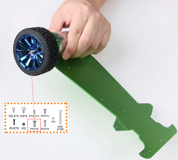
*Installieren sie die Räder auf dem Koppler mit den PM4*8 Schrauben. | |||
[[Datei:JetRacer_Motor_Hinterraeder_Step04.png|Step04]] | [[Datei:JetRacer_Motor_Hinterraeder_Step04.png|Step04]] | ||
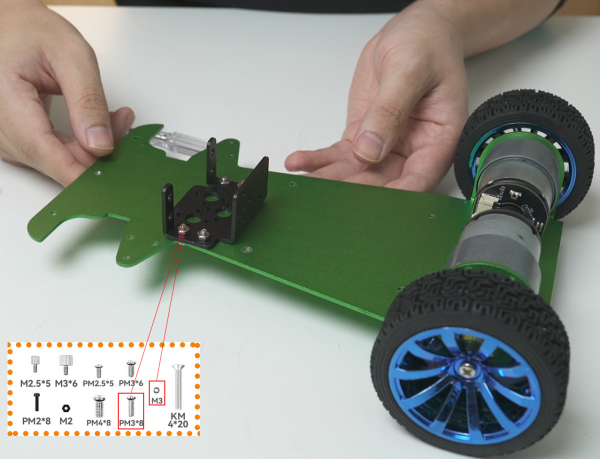
*Installieren sie die Servo Halterung auf der Karosserie. | |||
[[Datei:JetRacer_Motor_Hinterraeder_Step05.png|Step05]] | [[Datei:JetRacer_Motor_Hinterraeder_Step05.png|Step05]] | ||
== '''Teil 2: Zusammenbau Servo und Lenkung''' == | == '''Teil 2: Zusammenbau Servo und Lenkung''' == | ||
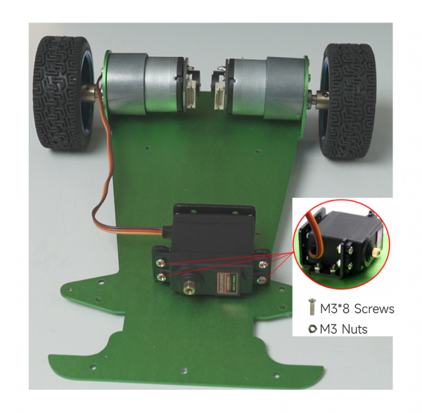
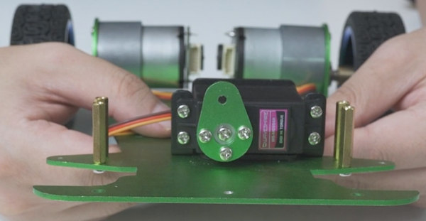
*Fixieren sie den Servo innerhalb der Halterung mit M3*8 Schrauben und M3 Muttern, achten sie dabei auf die Servo Ausrichtung. | |||
*Hierbei müssen vielleicht die Schraubenlöcher der Servohalterung heruntergefeilt werden, damit der Servo später nicht die darüberliegenden Teile blockiert. | |||
*Außerdem können Gummiringe als Stoßdämpfer zwischen Schrauben und Mutter platziert werden. | |||
[[Datei:JetRacer_Servo_Lenkung_Step01.jpg|Step01]] | [[Datei:JetRacer_Servo_Lenkung_Step01.jpg|Step01]] | ||
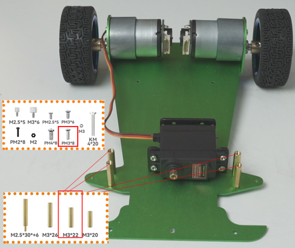
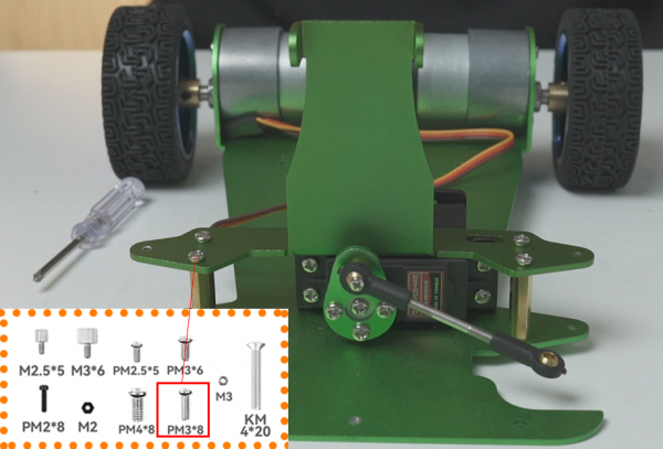
*Fix M3*22 standoffs with PM3*8. | |||
*Installieren sie die M3*22 Abstandshalter mit den PM3*8 Schrauben. | |||
[[Datei:JetRacer_Servo_Lenkung_Step02.png|Step02]] | [[Datei:JetRacer_Servo_Lenkung_Step02.png|Step02]] | ||
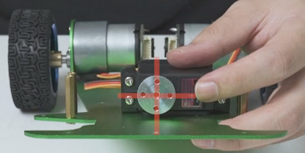
*Install the metal servo wheel on the servo, make sure that the holes of the servo wheel appear as a cross, and then install. If there is no cross, you can slowly rotate the servo wheel until a cross appears and then install it. | |||
*Befestigen sie das Metallrad des Servos an diesem, achten sie dabei darauf das die Löcher des Rads ein Kreuz bilden. Falls kein Kreuz zu erkennen ist, rotieren sie den Servo langsam solange bis ein Kreuz erscheint, und installieren sie das Rad dann. | |||
[[Datei:JetRacer_Servo_Lenkung_Step03.png|Step03]] | [[Datei:JetRacer_Servo_Lenkung_Step03.png|Step03]] | ||
*Fix the servo wheel fixing panel to the metal servo wheel with the included screws. | |||
*Fixieren sie den Aufsatz auf dem Rad mit den beigelegten Schrauben. | |||
[[Datei:JetRacer_Servo_Lenkung_Step04.png|Step04]] | [[Datei:JetRacer_Servo_Lenkung_Step04.png|Step04]] | ||
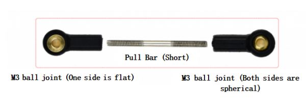
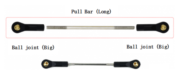
*Use two M3 ball joints (small) and a short rod to form the pull bar of the servo. Use two M3 ball joints (big) and a long rod to form the pull bar of the front wheel. The two ball heads are horizontal. | |||
[[Datei:JetRacer_Servo_Lenkung_Step05.png|Step05]] | [[Datei:JetRacer_Servo_Lenkung_Step05.png|Step05]] | ||
[[Datei:JetRacer_Servo_Lenkung_Step06.png|Step06]] | [[Datei:JetRacer_Servo_Lenkung_Step06.png|Step06]] | ||
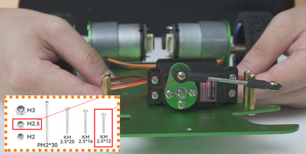
*Use KM2.5*12 screws and M2 self-lock nuts to fix the flat end of the pull bar on the servo. | |||
[[Datei:JetRacer_Servo_Lenkung_Step07.png|Step07]] | [[Datei:JetRacer_Servo_Lenkung_Step07.png|Step07]] | ||
*Install the camera bracket on the M3*22 standoffs by PM3*8. | |||
[[Datei:JetRacer_Servo_Lenkung_Step08.png|Step08]] | [[Datei:JetRacer_Servo_Lenkung_Step08.png|Step08]] | ||
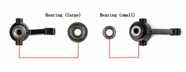
*Install the large and small bearings in the steering knuckle. | |||
[[Datei:JetRacer_Servo_Lenkung_Step09.png|Step09]] | [[Datei:JetRacer_Servo_Lenkung_Step09.png|Step09]] | ||
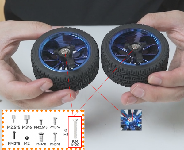
*Lock the wheel on the steering knuckle with KM4*20 screws and M4 self-lock nuts. Be careful not to lock it too loosely here to avoid shaking the front wheel of the car, and also not to lock it too tightly so that the front wheel cannot rotate normally. After the installation is completed, turn the wheel to test whether it can rotate smoothly. | |||
[[Datei:JetRacer_Servo_Lenkung_Step10.png|Step10]] | [[Datei:JetRacer_Servo_Lenkung_Step10.png|Step10]] | ||
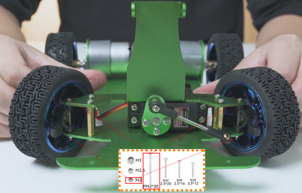
*Use PM2*30 screws and M2 self-lock nuts to install the front wheel on the JetRacer. Be careful not to lock it too tightly. After the installation is complete, turn it left and right to test whether it turns smoothly. | |||
[[Datei:JetRacer_Servo_Lenkung_Step11.png|Step11]] | [[Datei:JetRacer_Servo_Lenkung_Step11.png|Step11]] | ||
*Adjust the length of the servo pull bar so that when the servo is 90 degrees, the tires will not deflect towards the front. | |||
[[Datei:JetRacer_Servo_Lenkung_Step12.png|Step12]] | [[Datei:JetRacer_Servo_Lenkung_Step12.png|Step12]] | ||
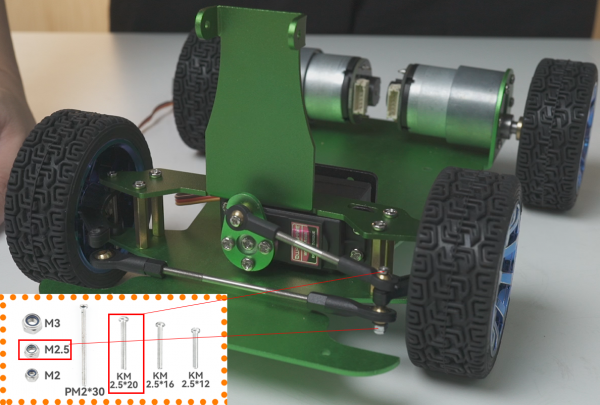
*Install the pull bars of the servo and front wheels on the steering knuckle with KM2.5*20 screws and M2.5 self-lock nut. Note that the servo rod is at the top, and the front pull rod is at the bottom. For the first time, you need to screw the screw into the hole of the steering cup. | |||
[[Datei:JetRacer_Servo_Lenkung_Step13.png|Step13]] | [[Datei:JetRacer_Servo_Lenkung_Step13.png|Step13]] | ||
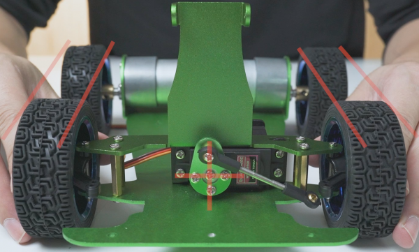
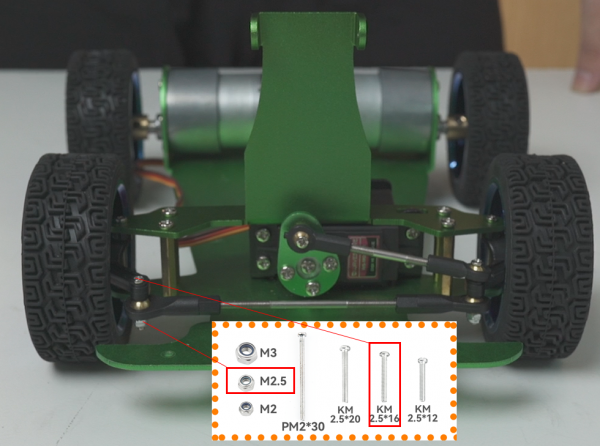
*Adjust the pull bar length of the front wheel so that the left and right wheels are parallel and facing straight ahead without deflection. Finally, use KM2.5*16 screws and M2.5 self-lock nuts to lock the pull bar of the front wheel to the steering knuckle. | |||
[[Datei:JetRacer_Servo_Lenkung_Step14.png|Step14]] | [[Datei:JetRacer_Servo_Lenkung_Step14.png|Step14]] | ||
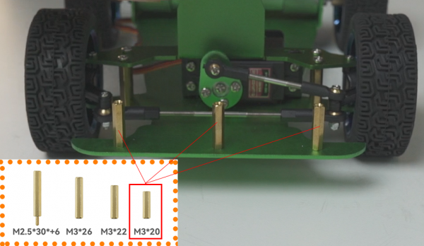
*Fix the standoffs (M3*20) for the anti-collision cotton with PM3*8. | |||
[[Datei:JetRacer_Servo_Lenkung_Step15.png|Step15]] | |||
*Install the anti-collision cotton and press the metal case on it with PM3*8. | |||
[[Datei:JetRacer_Servo_Lenkung_Step16.png|Step16]] | |||
== '''Teil 3: Installation Expansion Board und Jetson Nano Modul''' == | == '''Teil 3: Installation Expansion Board und Jetson Nano Modul''' == | ||
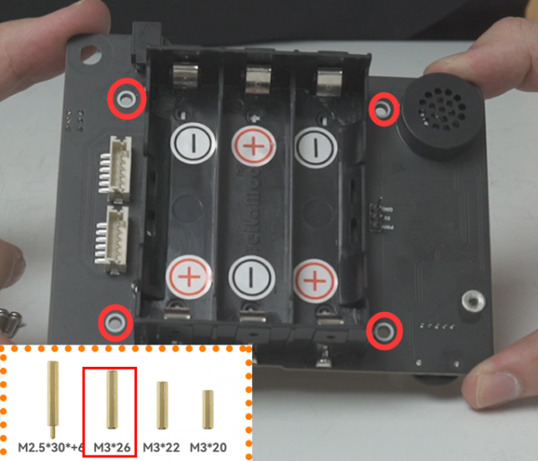
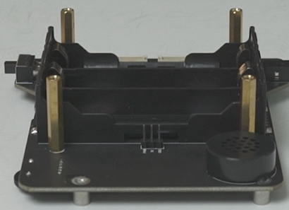
*Fix the standoffs on the expansion board with PM3*8. | |||
[[Datei:JetRacer_Expansion_Nano_Step01.png|Step01]] | |||
[[Datei:JetRacer_Expansion_Nano_Step02.png|Step02]] | |||
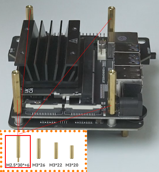
*Install the Jetson Nano module on the expansion board with M2.5*30 + 6. Note: Please remove the battery in this step! It is very easy to short-circuit and burn out when disassembling Jetson Nano while it is powered on. When the power switch of the expansion board is off, part of the circuit is still charged. | |||
[[Datei:JetRacer_Expansion_Nano_Step03.png|Step03]] | |||
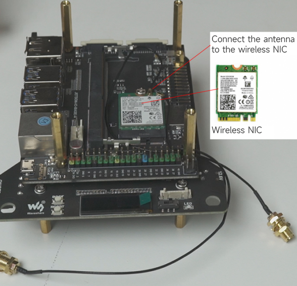
*Remove the Jetson Nano module, install the wireless NIC on the carrier board, and install the antenna. | |||
[[Datei:JetRacer_Expansion_Nano_Step04.jpg|Step04]] | |||
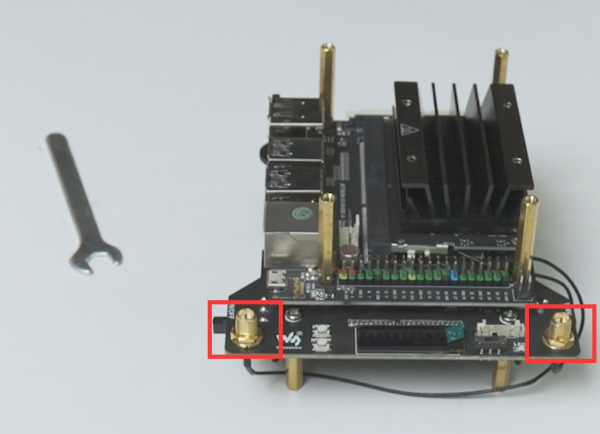
*Place the Jetson Nano module back, install one end of the antenna on the expansion board, and lock it with the spanner. | |||
[[Datei:JetRacer_Expansion_Nano_Step05.png|Step05]] | |||
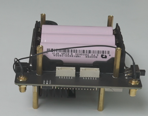
*Install the batteries. | |||
[[Datei:JetRacer_Expansion_Nano_Step06.png|Step06]] | |||
*Connect one end of the motor cable to the expansion board and the other end to the motor. Connect the servo cable to the expansion board and install the battery pad. | |||
[[Datei:JetRacer_Expansion_Nano_Step07.png|Step07]] | |||
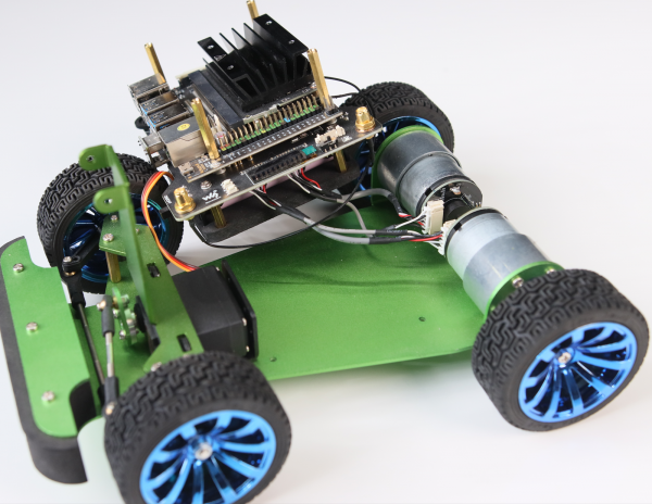
*Adjust the wiring of the servo and motor, and fix the expansion board to the chassis of the JetRacer with PM3*8 screws. | |||
[[Datei:JetRacer_Expansion_Nano_Step08.png|Step08]] | |||
*Install the cooling fan into the Jetson Nano with the included screws. Note that the label faces down, and connect the cooling fan power cable. | |||
[[Datei:JetRacer_Expansion_Nano_Step09.png|Step09]] | |||
== '''Teil 4: Installation Kamera und LIDAR''' == | == '''Teil 4: Installation Kamera und LIDAR''' == | ||
*Use black nylon screws PM2*8 to fix the camera, insulating sheet, and camera spacer together. | |||
[[Datei:JetRacer_Kamera_Lidar_Step01.png|Step01]] | |||
*Connect the camera cable, and fix the camera on the camera bracket with the flat screw M2.5*5. | |||
[[Datei:JetRacer_Kamera_Lidar_Step02.png|Step02]] | |||
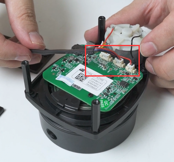
*Install radar cables. | |||
[[Datei:JetRacer_Kamera_Lidar_Step03.png|Step03]] | |||
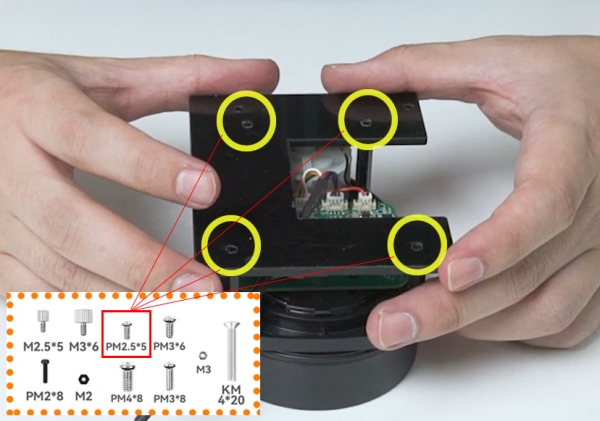
*Fix the acrylic panel to the radar with PM2.5*5. | |||
[[Datei:JetRacer_Kamera_Lidar_Step04.png|Step04]] | |||
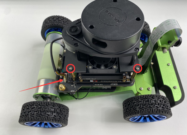
*Fix the radar on the M2.5*30 + 6 standoffs with PM2.5*5 screws, connect the radar cables. | |||
[[Datei:JetRacer_Kamera_Lidar_Step05.png|Step05]] | |||
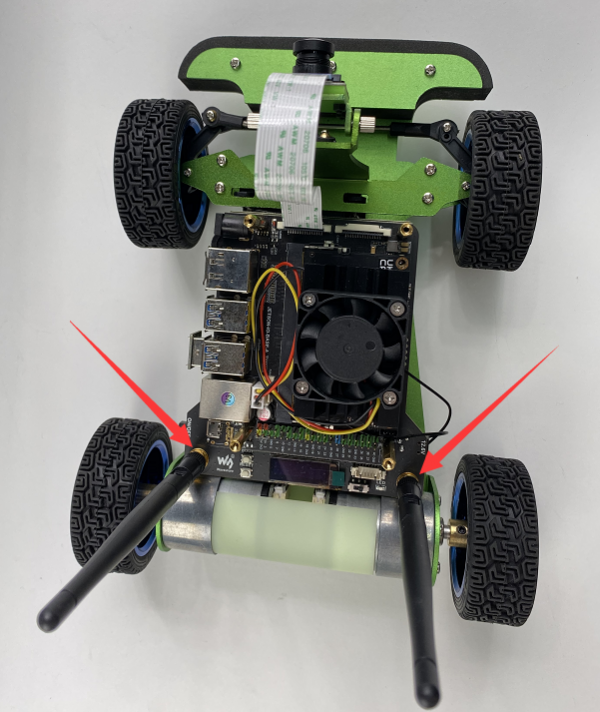
*Install the antenna. | |||
[[Datei:JetRacer_Kamera_Lidar_Step06.png|Step06]] | |||
*Install the USB connector and the motor case. Now the installation is complete. | |||
[[Datei:JetRacer_Kamera_Lidar_Step07.png|Step07]] | |||
*Es ist nun an der Zeit den JetRacer in Betrieb zu nehmen. | |||
Es ist nun an der Zeit den JetRacer in Betrieb zu nehmen. | *Quelle: [[https://www.waveshare.com/wiki/JetRacer_ROS_AI_Kit_Tutorial_I:_Assembly_Manual# JetRacer_ROS_AI_Kit_Tutorial_I:_Assembly_Manual]] | ||
Quelle: [[https://www.waveshare.com/wiki/JetRacer_ROS_AI_Kit_Tutorial_I:_Assembly_Manual# JetRacer_ROS_AI_Kit_Tutorial_I:_Assembly_Manual | |||
---- | ---- | ||
→ zurück zum Hauptartikel: [[ | → zurück zum Hauptartikel: [[Kategorie:JetRacer_ROS_AI_Roboter| Jetracer Ros AI Roboter]] | ||
Version vom 9. Dezember 2024, 17:20 Uhr
Autor: Jonas Beisler
Einleitung
Diese Bauanleitung bezieht sich auf den Bausatz JetRacer ROS AI Kit des Herstellers Waveshare.
Vorbereitung der Akkus
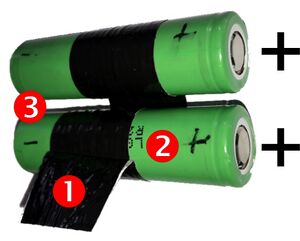
- Es hat sich gezeigt, dass die Akkus schwer aus dem Batteriefach zu entnehmen sind. Nutzen Sie einen Klebestreifen, um an jedem Akku eine Auszuglasche zu befestigen (① in Abb. 2). Die Auszuglasche wird am besten nahe des Minuspols angebracht.
- Um einer Verpolung von Akkus vorzubeugen, sollten Sie den Plus und Minuspol im ersten Schritt mit einem wasserfesten Stift beschriften (②, ③ in Abb. 2).
- Die Ausrichtung der Akkus im Batteriefach ist auf der Innenseite mit +/- Aufklebern markiert (①, ② in Abb. 3).)
- Achten Sie beim Einlegen der Akkus auf die korrekte Ausrichtung. Eine Verpolung kann zu Schäden oder Verletzungen führen.
Sicherheitshinweise

- Bitte beachten Sie, dass Lithium Zellen nur durch autorisiertes Fachpersonal verwendet werden dürfen.
- Lithium Zellen dürfen nur mit Schutzelektronik betrieben werden!
- Bei falscher Handhabung bzw. Kurzschluss kann dies zur Brandentwicklung oder Explosion führen.
- Laden Sie die Akkus ausschließlich mit dem Ladegerät im Set (Nitecore UM2).
- Die Bedienungsanleitung zum Ladegerät finden Sie hier.
- Lagern Sie die Akkus separat stets zu 80% geladen und vermeiden Sie eine Tiefenentladung.
- Beachten sie die allgemeingültigen Vorsichtsmaßnahmen für Akkus
- Akkus bei sichtbaren Beschädigungen oder Dellen nicht verwenden.
- nicht unbewacht laden,
- Temperatur überwachen,
- Akkus niemals tiefentladen oder überladen, zerlegen, ins Feuer oder Wasser werfen oder kurzschließen,
- Bitte Ihren Akku nie in der Hosentasche, Geldbörse oder einem anderen Behälter aufbewahren, wo sich Metallgegenstände befinden, um Kurzschluss und Verformung zu vermeiden.
- Akkus nicht entladen lagern, sondern abkühlen lassen und nach Benutzung und wieder aufladen,
- nicht hohen Temperaturen (>100°C z.B. Sonne) aussetzen.
- Bei technischen Problemen wenden Sie sich bitte an die Tutoren oder den betreuenden Mitarbeiter Marc Ebmeyer.
Vorbereitung vor der Montage
- Austesten des Expansion Bords und Servos
- Bauen sie die Batterien in das sogennante "Expansion Board" ein, schließen sie das Aufladekabel an und aktivieren sie den Batterieschutz.
- Nachdem die Batterie erfolgreich aktivitert wurde kann die Platine mit dem An/Aus-Schalter eingeschaltet werden. Die LED auf dem Board sollte dann aufblinken.
- Danach müssen sie den Servo an das Board anschließen. Dabei wird der Servo um 90° rotieren und so in deiner mittleren Position landen. Die Kabel Anordnung des Servos lautet: Gelb-PWM, Rot-5V und Braun-GND.
- AUSTESTEN DES NANO MODULS
- Quelle:[get Started jetson nano devkit]
Benötigte Werkzeuge
| Pos. | Anwendung |
|---|---|
| 1 | Kleine und Große Schraubendreher |
| 2 | Feile |
Teil 1: Zusammenbau Motor & Hinterräder
- Nutzen sie die M3*6 Schrauben um den Motor an der Metal Karosserie zu befestigen. Hier auf keinen Fall die langen Schrauben nutzen, da sonst der Motor nicht normal rotieren kann.
- Fixieren sie die Koppler-Schrauben auf dem Koppler mit dem passenden Schlüssel.
- Danach müssen sie den Koppler auf der Motorwelle installieren und die Schrauben festziehen. Die Schrauben müssen dabei auf der Wellenseite festgemacht werden
- Installieren sie die Räder auf dem Koppler mit den PM4*8 Schrauben.
- Installieren sie die Servo Halterung auf der Karosserie.
Teil 2: Zusammenbau Servo und Lenkung
- Fixieren sie den Servo innerhalb der Halterung mit M3*8 Schrauben und M3 Muttern, achten sie dabei auf die Servo Ausrichtung.
- Hierbei müssen vielleicht die Schraubenlöcher der Servohalterung heruntergefeilt werden, damit der Servo später nicht die darüberliegenden Teile blockiert.
- Außerdem können Gummiringe als Stoßdämpfer zwischen Schrauben und Mutter platziert werden.
- Fix M3*22 standoffs with PM3*8.
- Installieren sie die M3*22 Abstandshalter mit den PM3*8 Schrauben.
- Install the metal servo wheel on the servo, make sure that the holes of the servo wheel appear as a cross, and then install. If there is no cross, you can slowly rotate the servo wheel until a cross appears and then install it.
- Befestigen sie das Metallrad des Servos an diesem, achten sie dabei darauf das die Löcher des Rads ein Kreuz bilden. Falls kein Kreuz zu erkennen ist, rotieren sie den Servo langsam solange bis ein Kreuz erscheint, und installieren sie das Rad dann.
- Fix the servo wheel fixing panel to the metal servo wheel with the included screws.
- Fixieren sie den Aufsatz auf dem Rad mit den beigelegten Schrauben.
- Use two M3 ball joints (small) and a short rod to form the pull bar of the servo. Use two M3 ball joints (big) and a long rod to form the pull bar of the front wheel. The two ball heads are horizontal.
- Use KM2.5*12 screws and M2 self-lock nuts to fix the flat end of the pull bar on the servo.
- Install the camera bracket on the M3*22 standoffs by PM3*8.
- Install the large and small bearings in the steering knuckle.
- Lock the wheel on the steering knuckle with KM4*20 screws and M4 self-lock nuts. Be careful not to lock it too loosely here to avoid shaking the front wheel of the car, and also not to lock it too tightly so that the front wheel cannot rotate normally. After the installation is completed, turn the wheel to test whether it can rotate smoothly.
- Use PM2*30 screws and M2 self-lock nuts to install the front wheel on the JetRacer. Be careful not to lock it too tightly. After the installation is complete, turn it left and right to test whether it turns smoothly.
- Adjust the length of the servo pull bar so that when the servo is 90 degrees, the tires will not deflect towards the front.
- Install the pull bars of the servo and front wheels on the steering knuckle with KM2.5*20 screws and M2.5 self-lock nut. Note that the servo rod is at the top, and the front pull rod is at the bottom. For the first time, you need to screw the screw into the hole of the steering cup.
- Adjust the pull bar length of the front wheel so that the left and right wheels are parallel and facing straight ahead without deflection. Finally, use KM2.5*16 screws and M2.5 self-lock nuts to lock the pull bar of the front wheel to the steering knuckle.
- Fix the standoffs (M3*20) for the anti-collision cotton with PM3*8.
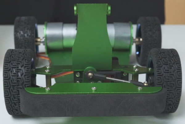
- Install the anti-collision cotton and press the metal case on it with PM3*8.
Teil 3: Installation Expansion Board und Jetson Nano Modul
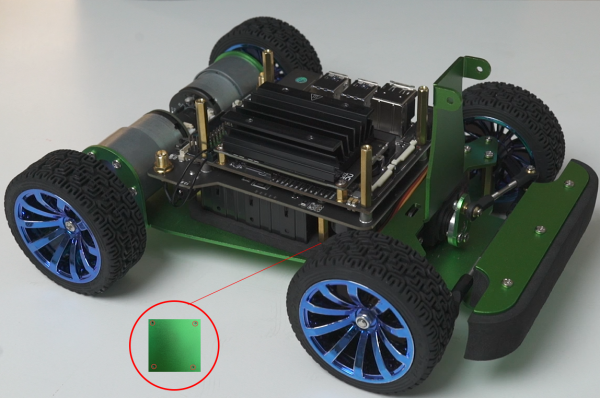
- Fix the standoffs on the expansion board with PM3*8.
- Install the Jetson Nano module on the expansion board with M2.5*30 + 6. Note: Please remove the battery in this step! It is very easy to short-circuit and burn out when disassembling Jetson Nano while it is powered on. When the power switch of the expansion board is off, part of the circuit is still charged.
- Remove the Jetson Nano module, install the wireless NIC on the carrier board, and install the antenna.
- Place the Jetson Nano module back, install one end of the antenna on the expansion board, and lock it with the spanner.
- Install the batteries.
- Connect one end of the motor cable to the expansion board and the other end to the motor. Connect the servo cable to the expansion board and install the battery pad.
- Adjust the wiring of the servo and motor, and fix the expansion board to the chassis of the JetRacer with PM3*8 screws.
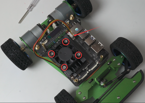
- Install the cooling fan into the Jetson Nano with the included screws. Note that the label faces down, and connect the cooling fan power cable.
Teil 4: Installation Kamera und LIDAR
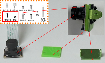
- Use black nylon screws PM2*8 to fix the camera, insulating sheet, and camera spacer together.
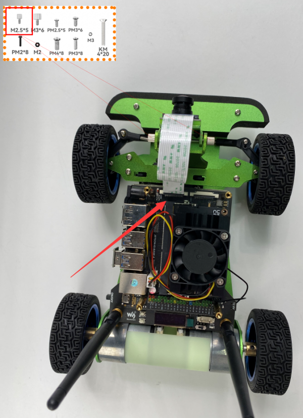
- Connect the camera cable, and fix the camera on the camera bracket with the flat screw M2.5*5.
- Install radar cables.
- Fix the acrylic panel to the radar with PM2.5*5.
- Fix the radar on the M2.5*30 + 6 standoffs with PM2.5*5 screws, connect the radar cables.
- Install the antenna.
- Install the USB connector and the motor case. Now the installation is complete.
- Es ist nun an der Zeit den JetRacer in Betrieb zu nehmen.
- Quelle: [JetRacer_ROS_AI_Kit_Tutorial_I:_Assembly_Manual]
→ zurück zum Hauptartikel:
